
Trough body for high-efficiency permanent magnet drum magnetic separator

A permanent magnet drum type, magnetic separator technology, applied in solid separation, magnetic separation, chemical instruments and methods, etc., can solve the problems of increasing the residence time of ore pulp, etc., to extend the separation time, overflow weir height, and sorting with long effect

Inactive Publication Date: 2011-07-27
LIAONING WUHUAN ENG TECH
View PDF0 Cites 0 Cited by
  • Summary
  • Abstract
  • Description
  • Claims
  • Application Information

AI Technical Summary

Problems solved by technology

In view of the requirement of high-efficiency permanent magnet drum magnetic separator for sorting operation, it is necessary to have a deep magnetic field with a high depth gradient in the sweeping area, so as to ensure that it can complete the complete recovery of strong magnetic minerals under the condition of large flow, and At present, the trough body for permanent magnetic drum magnetic separators on the market has defects due to its own structure, such as: for the requirements of high-efficiency permanent magnetic drum magnetic separators for sorting operations, the pulp throughput is 800m 3 ~1200m 3 / h, corresponding to the large wrap angle of the equipment and the characteristics of the long separation zone, a high overflow weir is configured to increase the residence time of the slurry; at the same time, the inclusion of concentrate is more obvious in the separation operation, and it is necessary to deal with the inclusion phenomenon to reduce the inclusion Improve concentrate grade

Method used


Image

  • Trough body for high-efficiency permanent magnet drum magnetic separator
  • Trough body for high-efficiency permanent magnet drum magnetic separator
  • Trough body for high-efficiency permanent magnet drum magnetic separator

Examples


example 1

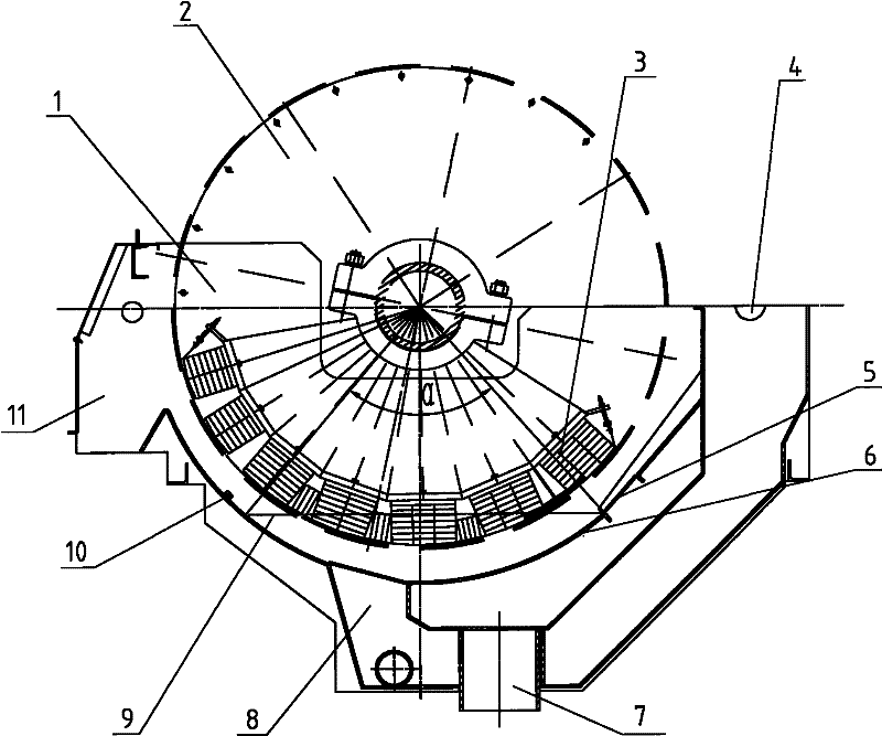
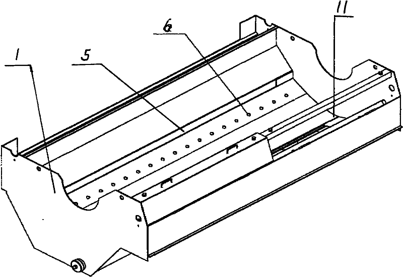
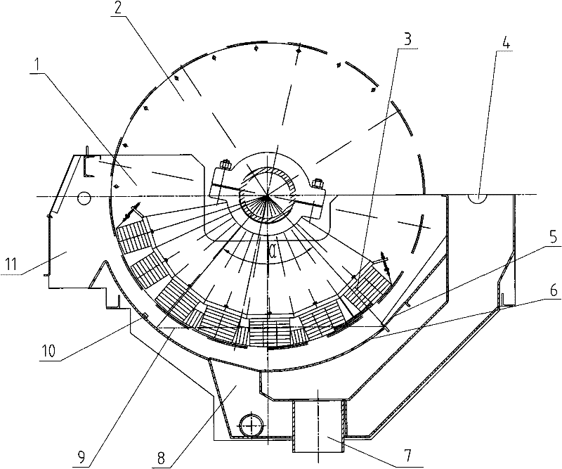
[0016] by Figure 1-2 As shown, 1 in the figure is a tank body 1 that is provided with a mine inlet 4 on the upper side and a tailings outlet 7 at the bottom and corresponding to the high-efficiency permanent magnet cylinder 2. The tank body 1 is welded by austenitic non-magnetic stainless steel The bottom surface of the tank body is provided with a mine inlet 8 connected to the ore inlet 4, and on the slope of the tank body on the same side as the ore inlet, there is an overflow connected with the tailings outlet. The outflow port 5 is provided with a coarse particle discharge hole 6 connected to the tailing outlet 7 in the tank body at the lower part of the overflow port; a concentrate outlet 11 is also provided on the upper part of the tank slope on the side opposite to the feeding inlet. In addition, 3 in the figure is the magnetic system in the permanent magnet cylinder.

[0017] The height of the overflow weir ranges from 180mm to 250mm, the magnetic wrap angle of the perm...


PUM


Abstract

The invention discloses a trough body for a high-efficiency permanent magnet drum magnetic separator, comprising a trough body, wherein the trough body is provided with an ore-feeding inlet at the upper part of one lateral surface and a tailing outlet at the lower part of the lateral surface and corresponds to a high-efficiency permanent magnet drum. In addition, the trough body adopts a semi-reverse current form. The trough body is characterized in that an ore inlet communicated with the ore-feeding inlet is arranged on the bottom surface in the trough body; an overflow port communicated with the tailing outlet is arranged on a slope surface in the trough body, which is positioned at the same side with the ore-feeding inlet; a coarse particle discharge hole communicated with the tailing outlet is formed in the trough body at the lower part of the overflow port; an ore concentrate outlet is arranged at the upper part of the slope surface of the trough body on the lateral surface opposite to the ore-feeding inlet; and a spraying device jetting to the permanent magnet drum is arranged in the trough body. The invention has the advantages of high overflow weir and long sorting band for delaying the sorting time. In addition, with the coarse particle prior discharge hole, the phenomenon that ore is blocked in the trough body can be effectively prevented. Spraying tubes are arrangedin an ore unloading area, so that ore concentrate sundries can be removed and the ore concentrate grade can be improved. The invention also has the characteristics of simple and reasonable structure,simple and convenient operation, long service life and the like.

Description

Technical field [0001] The invention relates to the technical field of high-efficiency magnetic separation equipment, in particular to a tank for a high-efficiency permanent magnet drum type magnetic separator. Background technique [0002] As we all know, magnetic separation equipment is an important separation equipment in the process of iron metal separation in mines. At present, there are two main types of magnetic separation equipment used in mines. One is disc magnetic separation and the other is drum magnetic. selected. With the continuous development of science and technology, in order to improve production efficiency, large-scale magnetic separation equipment is becoming larger, and the performance of professional magnetic separators designed for the magnetic separation operating environment is constantly improving. In response to the requirements of the high-efficiency permanent magnet cylinder magnetic separator sorting operation, it is necessary to have a deeper magn...

Claims


Application Information

Patent Timeline
Patent Type & Authority Patents(China)
IPC IPC(8): B03C1/10
Inventor 冯泉韩跃新姜磊袁致涛张宪伟郭小飞
Owner LIAONING WUHUAN ENG TECH
Learn More