Device for arranging embroidering bead tube for common embroidery machine

An embroidery machine and bead tube technology, applied in the direction of embroidery machine mechanism, embroidery machine, automatic control embroidery machine, etc., can solve the problems of reducing the competitiveness of embroidery fabrics and machine embroidery machinery, sewing bead tubes, and high labor intensity , to achieve the effect of improving grade and viewing, improving production efficiency and high degree of automation

Inactive Publication Date: 2010-08-11
王仁坤
View PDF10 Cites 28 Cited by
  • Summary
  • Abstract
  • Description
  • Claims
  • Application Information

AI Technical Summary

Problems solved by technology

It is well known that the production of machine embroidery products must be based on special machinery. However, although the current machine embroidery machine additional special device can add embroidery accessories to the fabric, it has very high requirements for accessories and can only be embroidered as continuous accessories. For bulk The accessories cannot be embroidered, and can only be solved by placing them manually or by hand sewing. For accessories with more complicated shapes such as bead tubes, they can only be sewn by hand, and the products sewn by hand are not only rough in workmanship, It is impossible to sew the bead tube precisely according to the requirements of the pattern, let alone sew the bead tube according to the design requirements of the pattern. At the same time, the labor intensity is high, the efficiency is very low, and the labor cost is expensive. Accuracy leads to poor ornamental quality, low quality and low added value of fabrics, which has been plagued by the entire embroidery industry and machine embroidery machinery manufacturing industry. Competitiveness

Method used


Image

  • Device for arranging embroidering bead tube for common embroidery machine
  • Device for arranging embroidering bead tube for common embroidery machine
  • Device for arranging embroidering bead tube for common embroidery machine

Examples


Embodiment 1

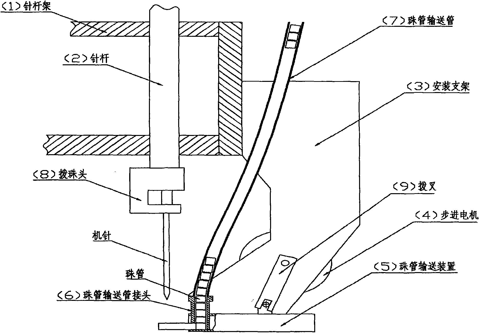
[0015] Embodiment 1: as figure 1 As shown, the ordinary embroidery machine is equipped with a device for embroidery bead tubes, including: needle bar frame 1, needle bar 2, mounting bracket 3, stepping motor 4, bead tube delivery device 5, bead tube delivery pipe joint 6, bead tube Pipe delivery pipe 7, bead dial head and machine needle 8, and shift fork 9, needle bar 2 is installed in the needle bar frame 1, and the side is fixed with the mounting bracket 3, and the stepping motor 4 is fixed in the middle of the mounting bracket 3, The bead tube delivery device 5 is fixed on the lower part of the mounting bracket 3, the bead tube delivery device 5 is movably connected with the stepper motor 4 through a shift fork 9, the bead tube delivery pipe joint 6 is mounted on the front plane of the bead tube delivery device 5, and the bead tube delivery device 5 is mounted on the front plane of the bead tube delivery device 5. The pipe conveying pipe 7 is connected with the bead pipe co...

Embodiment 2

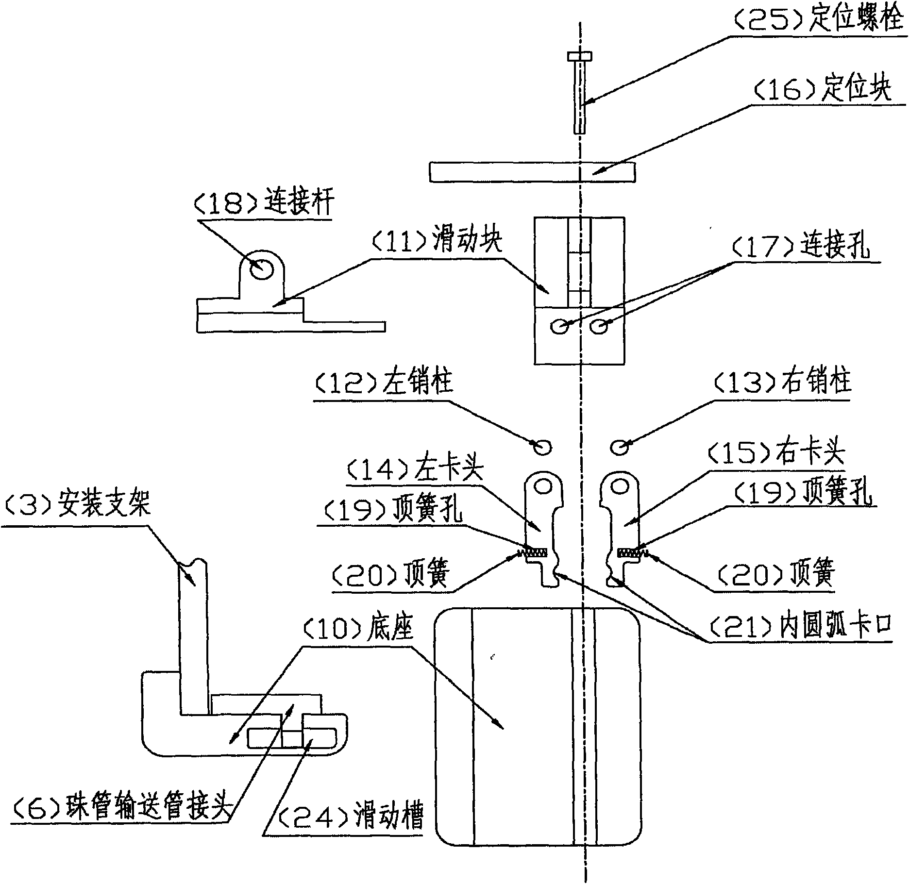
[0016] Embodiment 2: as figure 1 and figure 2 As shown, the ordinary embroidery machine is equipped with a bead tube conveying device for embroidery bead tubes, including: a base 10, a sliding block 11, a left pin 12, a right pin 13, a left clamping head 14, a right clamping head 15, positioning Block 16, sliding groove 24 and positioning bolt 25, sliding block 11, left pin 12, right pin 13, left chuck 14 and right chuck 15 are all assembled in sliding groove 24, left chuck 14 and right chuck 15 is movably connected with the connecting hole 17 located at the front of the sliding block 11 through the left pin 12 and the right pin 13, the positioning block 16 is fixed on the rear end of the base 10, the positioning bolt 25 is fixed in the positioning block 16, and the sliding block 11 The upper part is fixed with a connecting rod 18 that is movably connected with the fork 9. The contact point between the front end and the backstop bead position 22 of the bead pipe delivery pip...

Embodiment 3

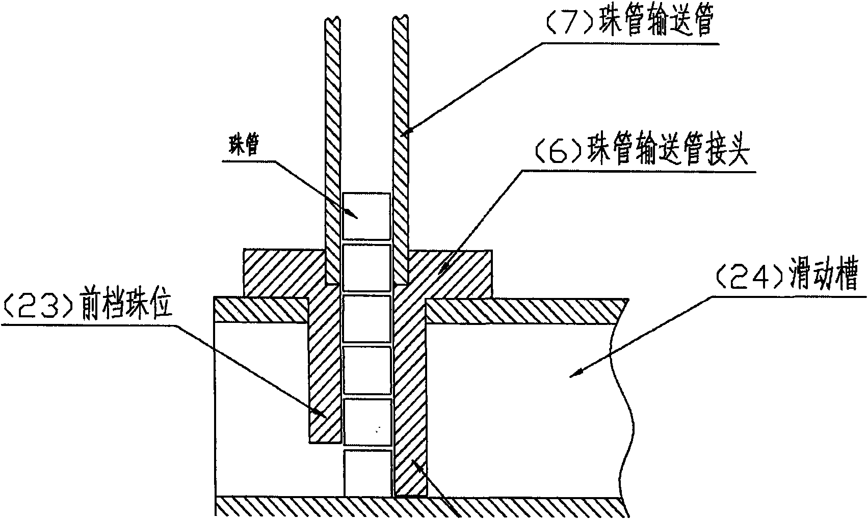
[0017] Embodiment 3: as figure 1 , figure 2 and image 3 As shown, the common embroidery machine is equipped with the bead pipe delivery pipe joint and the bead pipe delivery pipe of the bead pipe embroidery device, including: a backstop bead position arranged on the rear side of the lower part of the bead pipe delivery pipe joint 6 to prevent the bead pipe from retreating 22. The front stop bead position 23 on the front side of the lower part to prevent the bead tube from falling forward. The bottom plane of the groove contacts, and the end face of the front retaining bead position and the bottom plane of the slide groove have a gap slightly higher than the height of a single bead tube, and the bead tube delivery pipe 7 is a spring type delivery tube.


PUM


Abstract

The invention discloses a device for arranging an embroidering bead tube for a common embroidery machine, which comprises that: a bead shifting head and a machine needle are fixed on the lower part of a needle rod in a needle rod frame; a mounting bracket is fixed on the side face of the needle rod frame; a stepping motor is fixed in the middle of the mounting bracket; a bead tube conveying device is fixed on the lower part of the mounting bracket and is movably connected with the stepping motor through a shifting fork; a bead tube conveying pipe joint is arranged on the front plane of the bead tube conveying device; and the bead tube conveying pipe is connected with the bead tube conveying pipe joint. The device has the advantages that: the device has simple and reasonable structure and convenient operation, and can accurately feed unpackaged bead tubes to the underside of the machine needle of the common embroidery machine, so that the bead tubes are embroidered on shell fabrics according to the requirement on patterns through holes in the bead tubes by the machine needle, the production efficiency is high, the droppoints of the embroidered patterned bead tubes are accurate, the shell fabrics are brilliant and attractive, the level and ornamental property of the shell fabrics are greatly improved, and the like.

Description

technical field [0001] The invention relates to a device for adding an embroidery bead tube to an ordinary embroidery machine, especially related to the machine embroidery equipment in the sewing equipment. Background technique [0002] Machine embroidery fabrics have the characteristics of full pattern, strong three-dimensional effect, colorful colors, and can be positioned according to the requirements of clothing, etc. The fabrics embroidered with other auxiliary materials are even more ornamental, and the clothing is personalized and of high quality. advantage. At present, high-grade clothing fabrics (especially women's clothing) at home and abroad are all developing towards the direction of embellishment with embroidery. It is well known that the production of machine embroidery products must be based on special machinery. However, although the current machine embroidery machinery can add embroidery accessories to the fabric, its requirements for accessories are very h...

Claims


Application Information

Patent Timeline
Patent Type & Authority Applications(China)
IPC IPC(8): D05C7/02D05C13/00
Inventor 王仁坤
Owner 王仁坤
Why Eureka
Try Eureka