PPM (Pulse Position Modulation) coding synchronous demodulation method

A synchronous demodulation and encoding technology, which is applied in the field of infrared remote control encoding and decoding, can solve the problems of complicated program code decoding process, logic bit carrier width determination, and MCU resource consumption, and achieve machine code saving, program code structure simplicity, MCU The effect of saving resources

Inactive Publication Date: 2013-03-20
邳州市滨河中小企业管理服务有限公司
View PDF0 Cites 0 Cited by
  • Summary
  • Abstract
  • Description
  • Claims
  • Application Information

AI Technical Summary

Problems solved by technology

[0003] For the PWM modulation method, there is a series of carriers between each logical bit, and the number of logical bits corresponds to the number of low levels after the carrier, so the demodulation process only needs to determine the width of the low level after the carrier. Logic bits can be determined, decoding is relatively simple and the method is single
For PPM encoding, because there is no specific delimiter for adjacent logic bits, this brings at least three obstacles to the decoding process: the first is the definition of logic bits; the second is the determination of the number of logic bits; the third is , logic bit carrier width determination
The traditional PPM decoding method separates the error detection of the carrier, the definition of the logic bit, and the data restoration in sequence, resulting in an extremely complicated process of program code decoding and a great consumption of MCU resources.

Method used


Image

  • PPM (Pulse Position Modulation) coding synchronous demodulation method
  • PPM (Pulse Position Modulation) coding synchronous demodulation method
  • PPM (Pulse Position Modulation) coding synchronous demodulation method

Examples


Embodiment Construction

[0032] The content of the present invention will be further described below in conjunction with the accompanying drawings and specific embodiments.

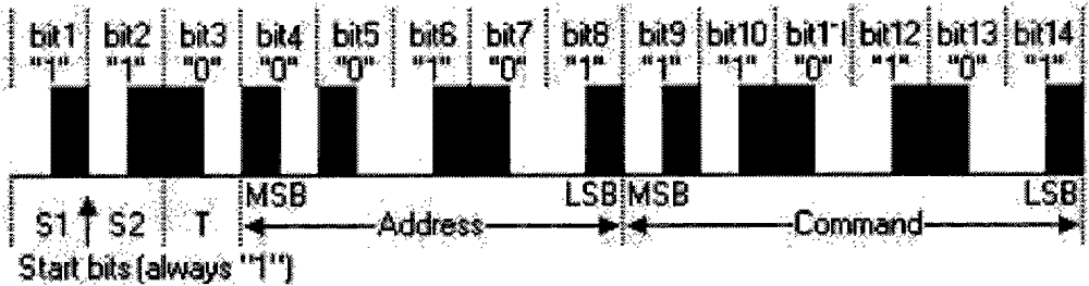
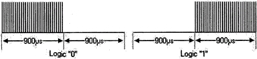
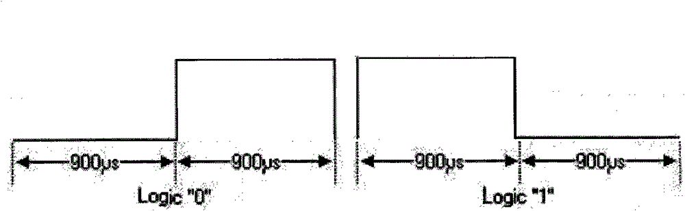
[0033] In this embodiment, Philips RC5 (3010) is taken as an example to illustrate the process of demodulating PPM encoding by MCU using the method of the present invention. Such as figure 1 Shown is the structure of the RC5 code pattern, where S1 / S2 is a fixed pilot code, and T is a parity check code. Such as figure 2 Shown is the logic bit 0 and 1 of the RC5 encoding method, and as image 3 Shown is the corresponding pulse of logic bit 0 and 1 outputted by the RC5 code after filtering by the infrared integrated receiving head, that is, the waveform received by the input pin of the MCU (when the infrared integrated receiving head has a carrier input pulse input, the filtered Carrier output low level, no carrier input, maintain high level output).

[0034] The following is the implementation steps of receiving level error de...


PUM


Abstract

The invention relates to a PPM (Pulse Position Modulation) coding synchronous demodulation method which comprises the steps of: setting an actual level bit zone, judging a coding logic bit according to the actual level bit zone when the PPM coding level is changed, confirming the validity of the level by using carrier error detection, and adjusting the level bit zone so as to complete the level validity confirmation and the data recovery while in logic definition and realize the synchronous demodulation of PPM coding. The invention has the advantages that: the decoding process of the PPM coding is greatly simplified by using a mode of simultaneously carrying out carrier error detection, logic bit definition and data recovery, and the efficiency is obviously improved; the program structure is clear and simple; MCU (Microprogrammed Control Unit) resources are saved and machine codes are saved by 40 percent; and less variables, inlets and outlets ensure that the program is easy to control and transplant with high stability.

Description

technical field [0001] The invention specifically relates to a demodulation method of PPM encoding which can perform carrier error detection, logic bit definition and data restoration synchronously in the technical field of infrared remote control encoding and decoding. Background technique [0002] In the field of infrared remote control coding and decoding technology, the basic structure of a frame of data is: boot code + data (a series of logic bits) + end bits, and the coding methods of commonly used logic bits mainly include PPM (Pulse Position Modulation) and PWM (Pulse Width Modulation) Two kinds. The PWM encoding is a series of carrier waves + a period of low level, which distinguishes different logic bits by the width of the low level, while the PPM encoding method distinguishes logic bits by the position of a series of carrier waves and a period of low level. [0003] For the PWM modulation method, there is a series of carriers between each logical bit, and the nu...

Claims


Application Information

Patent Timeline
Patent Type & Authority Patents(China)
IPC IPC(8): H03M13/03H03M13/11
Inventor 曹明润贾力马春龙徐君怡
Owner 邳州市滨河中小企业管理服务有限公司
Why Eureka
Try Eureka