A scanning electron microscope

A technology of electron microscope and electron gun, which is applied in the direction of circuits, discharge tubes, electrical components, etc., can solve the problems of shortening the life of SEM, and achieve the effect of compact structure, high vacuum degree and long life

Inactive Publication Date: 2010-08-11
赛可株式会社
View PDF0 Cites 2 Cited by
  • Summary
  • Abstract
  • Description
  • Claims
  • Application Information

AI Technical Summary

Problems solved by technology

As a result, the lifetime of the SEM is shortened

Method used


Image

  • A scanning electron microscope
  • A scanning electron microscope
  • A scanning electron microscope

Examples


Embodiment Construction

[0025] Matters defined in the specification, such as detailed structures and elements, are provided to assist in a comprehensive understanding of the exemplary embodiments of the present invention. Accordingly, those of ordinary skill in the art will recognize that various changes and modifications of the embodiments described herein can be made without departing from the scope and spirit of the invention. Also, descriptions of well-known functions and constructions are omitted for clarity and conciseness.

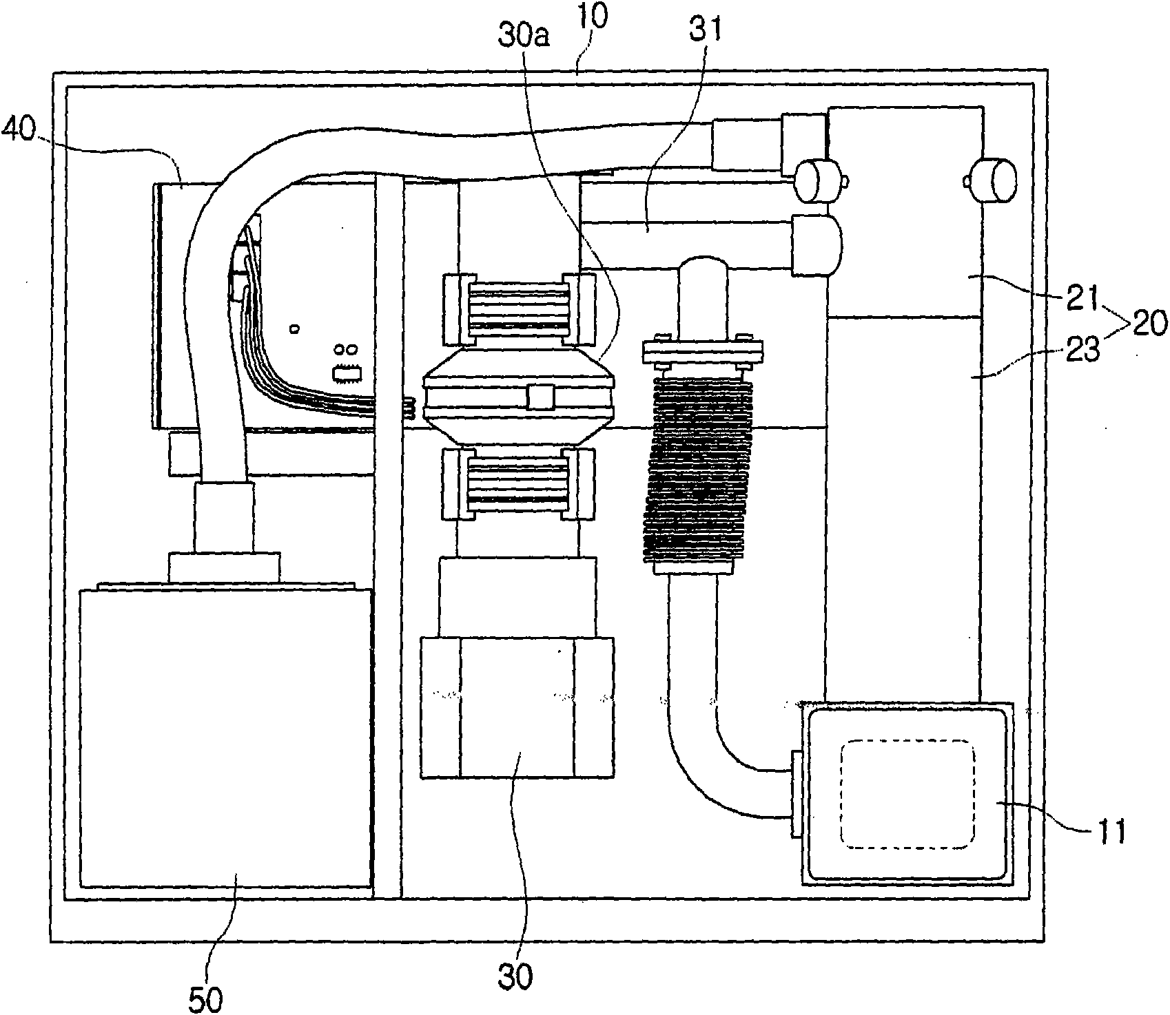
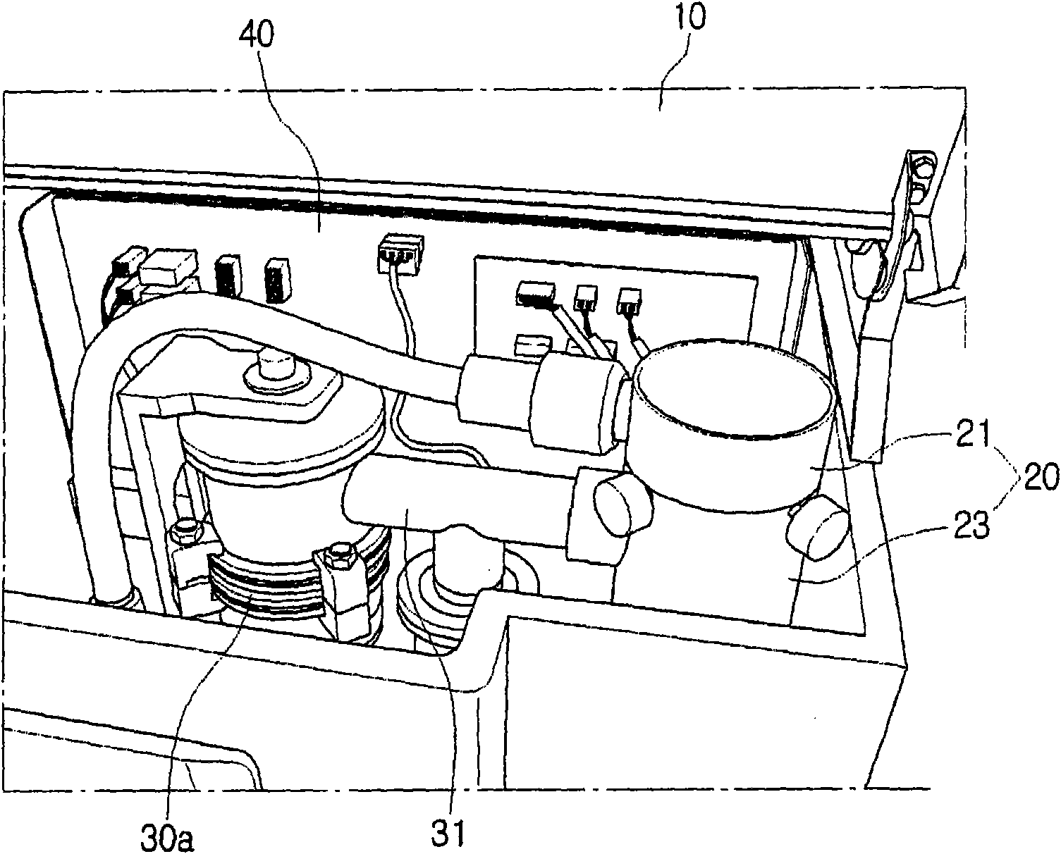
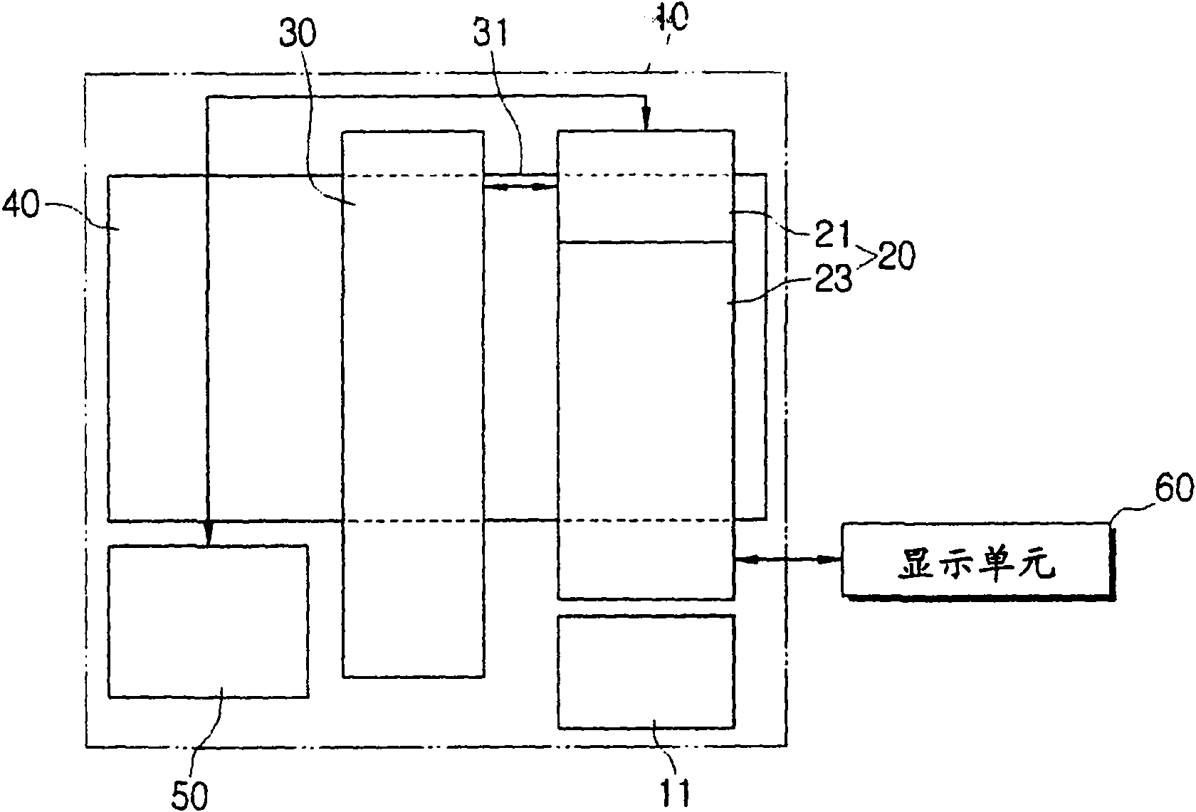
[0026] see figure 1 , a scanning electron microscope (SEM) according to an exemplary embodiment of the present invention may include a SEM main body 10 , an electron optical unit 20 , a vacuum pump 30 and a control unit 40 . For reference only, an element indicated with reference numeral 50 is a high voltage generating unit to supply high voltage to the electron optical unit 20 .

[0027] Such as figure 1 , 3 As shown in 4, the SEM main body 10 includes a sample holder...


PUM


Abstract

A scanning electron microscope (SEM) having a simple structure and an improved degree of vacuum is provided. A scanning electron microscope (SEM) according to the present invention includes a SEM main body having a sample holder, an electro-optical unit installed on the SEM main body perpendicularly to the sample holder to be opposed to the sample holder, a vacuum pump installed inside the SEM main body in parallel to the electro-optical, and a control unit installed inside the SEM main body to control the electro-optical unit.

Description

technical field [0001] The present invention relates to a scanning electron microscope that magnifies and displays an image of a sample in a vacuum by scanning the sample with an electron beam. Background technique [0002] A scanning electron microscope (SEM) is a device used to magnify an image of a sample for observation. The SEM includes an electron optical unit to magnify an image of a sample, a control unit to control the electron optical unit, and a vacuum pump to create a vacuum in the electron optical unit. [0003] The electron optical unit includes an electron gun to generate electrons, a lens unit to guide an electron beam emitted from the electron gun to a sample in a sample holder, and a scanning coil to scan the electron beam onto the sample. Images obtained by the electron optical unit may be displayed on a display unit such as a computer or stored in a storage device and printed. [0004] Recently, the demand for compact SEMs has risen due to the growing n...

Claims


Application Information

Patent Timeline
IPC IPC(8): H01J37/26
CPCH01J2237/1825H01J2237/2801H01J37/065H01J2237/063H01J37/28H01J37/18H01J37/04H01J37/26
Inventor 金兴福郭京一全柄喆李仁揆金钟显
Owner 赛可株式会社
Why Eureka
Try Eureka