Radiological imaging method and device

A radioactive and imaging technology, applied in the clinical application of radiological diagnosis, equipment for radiological diagnosis, image enhancement, etc., can solve the problems of complex preprocessing

Inactive Publication Date: 2010-08-18
GENERAL ELECTRIC CO
View PDF10 Cites 18 Cited by
  • Summary
  • Abstract
  • Description
  • Claims
  • Application Information

AI Technical Summary

Problems solved by technology

However, this type of preprocessing is complex to implement and does not necessarily yield satisfactory results

Method used


Image

  • Radiological imaging method and device
  • Radiological imaging method and device
  • Radiological imaging method and device

Examples


Embodiment Construction

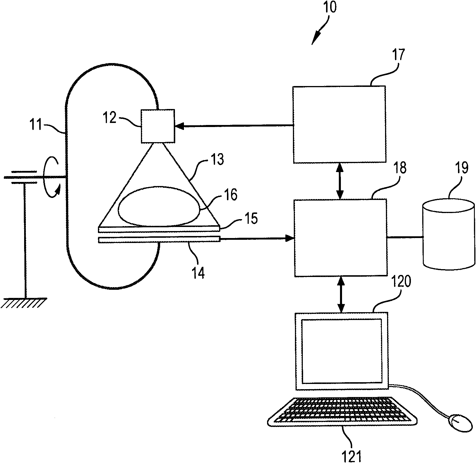
[0045] figure 1 In the shown apparatus 10 comprises a rotating arm 11 (C-arm), a source 12 fixed to one end of the rotating arm and capable of emitting radiation 13, and a detector 14 fixed to the other end of the rotating arm and capable of receiving radiation emitted by the source. The device 10 also includes a support 15 on which the patient can be placed, the support being designed such that the patient's region of interest 16 is located between the source 12 and the detector 14 . In this way, the detector 14 receives the X-rays emitted by the source 12 after they have passed through the region of interest 16 .

[0046] The acquisition device 10 comprises a control unit 17 capable of controlling the movement of the swivel arm 11 to various positions and capable of controlling the source 12 so that it emits radiation with a controllable energy level.

[0047] The acquisition device 10 also includes a computer processing unit 18 capable of receiving and processing the image...


PUM


Abstract

A method for radiological imaging of a region of interest including blood vessels. The method has the steps of acquiring a real-time fluoroscopic image of the region of interest by exposing the region of interest to a first dose of X-rays, the fluoroscopic image showing background structures and instrument introduced into the vessels; subtracting a mask image from the acquired real-time fluoroscopic image to generate a subtracted fluoroscopic image showing only the instrument; combining the subtracted fluoroscopic image and a pre-recorded diagnostic image of the region of interest showing only the blood vessels to generate a combined image showing both the blood vessels and the instrument; and displaying the combined image on a screen for viewing. The mask image is determined from a fluoroscopic image acquired prior to the introduction of the instrument into the vessels by exposing the region to an X-ray does equivalent to the first dose.

Description

technical field [0001] The present invention relates to methods and devices for radiological imaging intended for fluoroscopy-guided vascular surgery applications. Background technique [0002] During a vascular surgical intervention, a surgeon introduces an instrument (eg, guide, catheter, stent) into a blood vessel and moves it to the lesion to be treated. [0003] In order to be able to guide the movement of the instrument during the intervention procedure, the surgeon refers to an image of the area to be treated. These images include, on the one hand, mapped images of blood vessels (called "roadmaps") taken before the intervention, and on the other hand, fluoroscopic images taken in real time during the intervention procedure, which show the extent of the area being treated. Appliances and background structures (e.g. bone and soft tissue). [0004] Techniques have been proposed for showing the instrument position and vessel mapping on a single image to enable the surge...

Claims


Application Information

Patent Timeline
Patent Type & Authority Applications(China)
IPC IPC(8): A61B6/00A61B19/00A61B6/12H04N5/325
CPCA61B6/5235A61B6/481G06T5/50A61B6/12A61B6/504
Inventor J·利埃纳R·维兰B·勒尼P·-L·格奥尔吉
Owner GENERAL ELECTRIC CO
Why Eureka
Try Eureka