
Dual-direction pre-tensioning system prestressed concrete track slab

A track slab and prestressing technology, applied in tracks, roads, ballast layers, etc., can solve problems such as cracks or fractures of track slabs, increased cost of track slabs, low production efficiency, etc., and achieves improved service life, simple construction, and structural reasonable effect

Inactive Publication Date: 2010-08-18
欧阳炎
View PDF6 Cites 17 Cited by
  • Summary
  • Abstract
  • Description
  • Claims
  • Application Information

AI Technical Summary

Problems solved by technology

[0003] The track slab laid on the roadbed is under the pressure from the two steel rails. Over time, the track slab is often cracked or broken due to external force deformation, thus causing unnecessary losses. At the same time, it is also very inconvenient to maintain. ; For this reason, in the manufacturing process of track slabs, steel bars or steel strands or steel rods or steel wires are often set in the track slabs and prestressed to reduce the deformation of the track slabs caused by external forces; The application of slab prestress can adopt pre-tensioning method and post-tensioning method. In practical applications, most of the existing track slabs are prestressed post-tensioned concrete track slabs. The manufacturing process of prestressed post-tensioned concrete track slabs is simple, but the production efficiency It is very low, and a large number of anchors are needed to anchor the prestressed tendons. Moreover, the existing track slabs usually have steel cages made of coated steel bars to solve the transfer strength requirements of the track slabs after demoulding. Both make the cost of the track plate greatly increased

Method used


Image

  • Dual-direction pre-tensioning system prestressed concrete track slab
  • Dual-direction pre-tensioning system prestressed concrete track slab
  • Dual-direction pre-tensioning system prestressed concrete track slab

Examples


Embodiment Construction

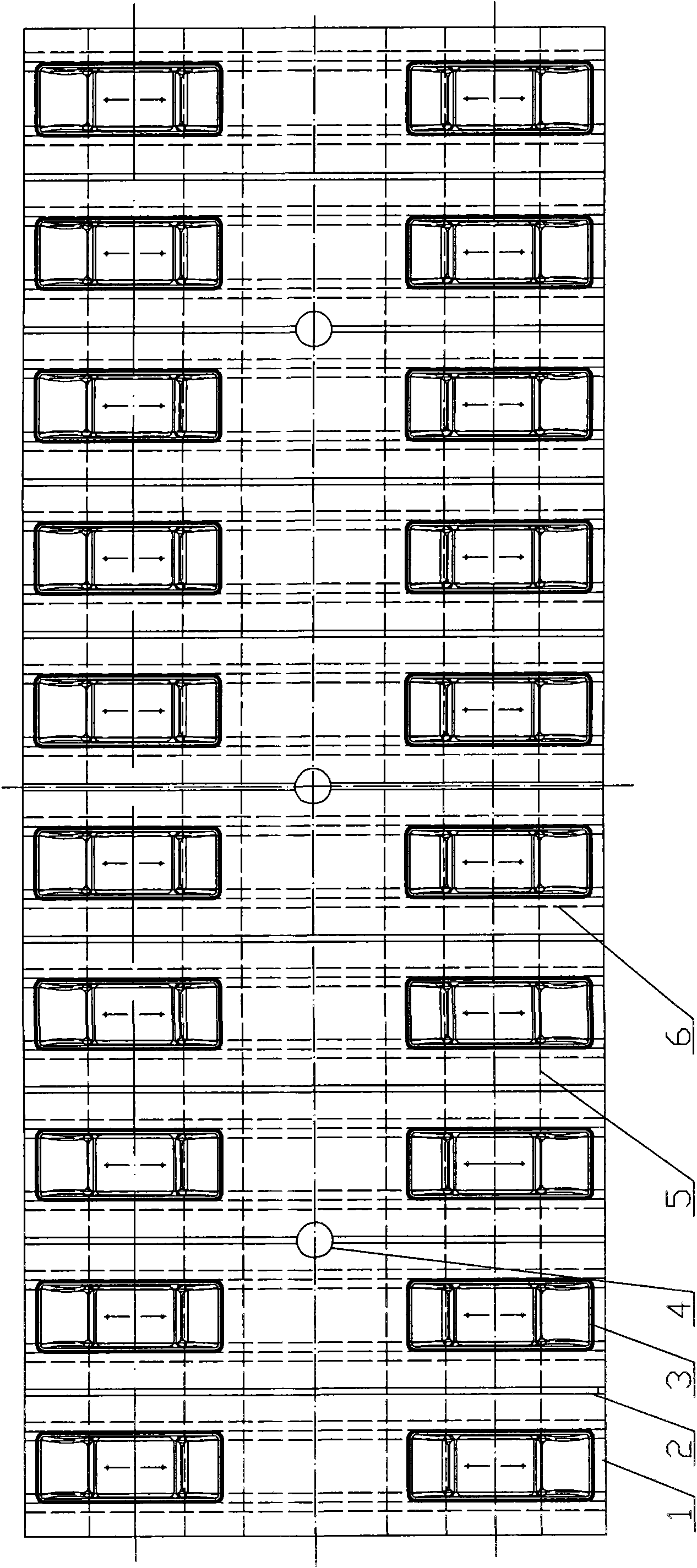
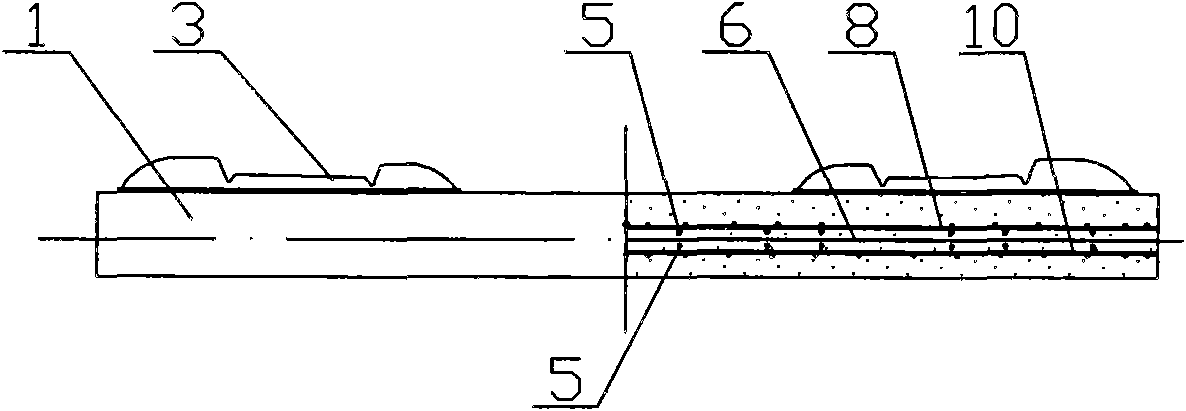
[0013] Depend on Figure 1-Figure 3 A two-way pre-tensioning method prestressed concrete track slab is shown, including a rectangular track slab body 1, and the upper surface of the track slab slab body 1 is provided with a rail part 3 and a groove 2 at intervals, and the groove 2 is arranged in the adjacent Between the two supporting rail parts 3, a structure 4 is reserved on the track plate body 1, and a steel bar layer is horizontally arranged in the track plate body 1, and the steel bar layer includes a longitudinal steel bar layer and a transverse The reinforcing bars 5 and 6 in the layers are arranged at intervals, the reinforcing bars 5 in the longitudinal reinforcing bar layer extend along the length direction of the track plate body 1, and the reinforcing bars 6 in the horizontal reinforcing bar layer extend along the width direction, including the upper and lower steel meshes arranged evenly and horizontally. 8, 10, the upper steel wire mesh 8, the longitudinal reinf...


PUM


Abstract

The invention discloses a dual-direction pre-tensioning system prestressed concrete track slab, which comprises a rectangular track slab body, wherein the track slab body is provided with a reservation structure, an upper layer steel wire net, a longitudinal reinforced bar layer, a transverse reinforced bar layer, a longitudinal reinforced bar layer and a lower layer steel wire net are sequentially arranged at intervals inside the track slab body along the thickness direction from top to bottom, steel bars inside the longitudinal reinforced bar layer extend in the length direction of the track slab body, steel bars inside the transverse reinforced bar layer extends in the width direction, the steel bars both in the longitudinal and the transverse reinforced bar layers are arranged at intervals, the transverse reinforced bar layer is arranged on a neutral axis of a cross section of the track slab body, and the two longitudinal reinforced bar layers and the upper and the lower steel wire nets are symmetrically and horizontally arranged relatively to the neutral axis of the cross section; and the prestressed concrete track slab is pre-tensioned along the length direction and the width direction, and the steel bar is of a prestressed steel bar. The dual-direction pre-tensioning system prestressed concrete track slab has simple structure and can strengthen the strength of the track slab.

Description

technical field [0001] The invention relates to the technical field of high-speed railway tracks, and furthermore, relates to a bidirectional pre-tensioned prestressed concrete track slab suitable for slag-free tracks of high-speed railways. Background technique [0002] With the continuous development of science and technology, the slag-containing track has been gradually eliminated due to various disadvantages, while the slag-free track has gradually been gradually eliminated in the construction of high-speed railway due to its high reliability, high smoothness, high durability and almost no track maintenance. Adopted, but the key technology of the slag-free track lies in the track plate and its manufacturing process. [0003] The track slab laid on the subgrade is subjected to the pressure from the two rails. Over time, the track slab is often cracked or broken due to the deformation of external force, thus causing unnecessary losses and at the same time, it is also very ...

Claims


Application Information

Patent Timeline
IPC IPC(8): E01B1/00E01B3/34E04C5/01E04C5/08
Inventor 欧阳炎
Owner 欧阳炎
Learn More