
Vertical centrifugal hydroextractor

A vertical centrifuge and dehydrator technology, applied in the direction of drying solid materials, sustainable manufacturing/processing, chemical industry, etc., can solve the problems of reducing machine reliability, high equipment manufacturing costs, scraper and screen wear, etc., to achieve Eliminate scraping and pushing wear and energy consumption, simple and compact structure, accurate and reliable action

Active Publication Date: 2010-08-18
张学骞
View PDF0 Cites 19 Cited by
  • Summary
  • Abstract
  • Description
  • Claims
  • Application Information

AI Technical Summary

Problems solved by technology

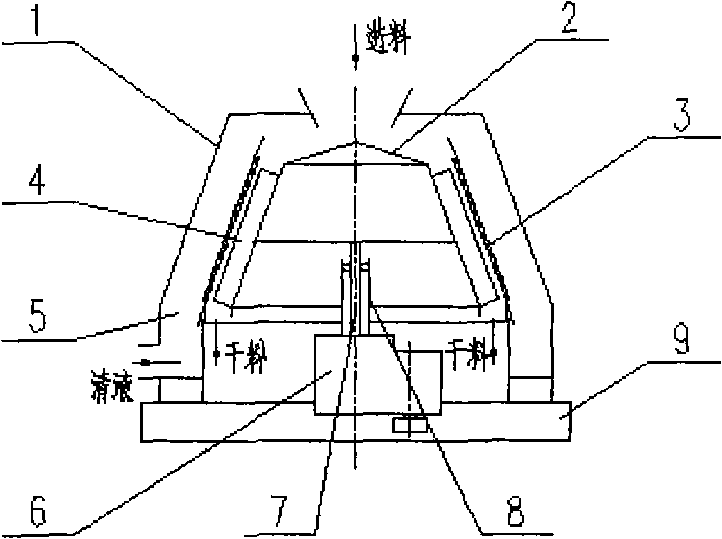
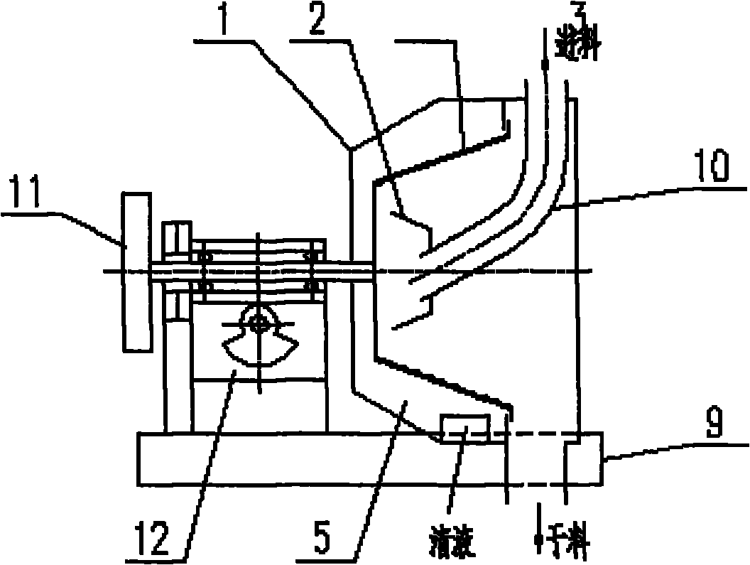
[0005] The above-mentioned first type of centrifugal dehydrator is mainly used for dehydration of materials with a particle size of 0.5mm or more. The problem of the scraper discharge centrifugal dehydrator is: scraper and screen wear Serious, low life, high energy consumption
Vibrating unloading centrifugal dehydrator has poor adaptability to different materials, and it is often difficult to unload due to the nature of the material and the amount of input material, which reduces the reliability of the machine.
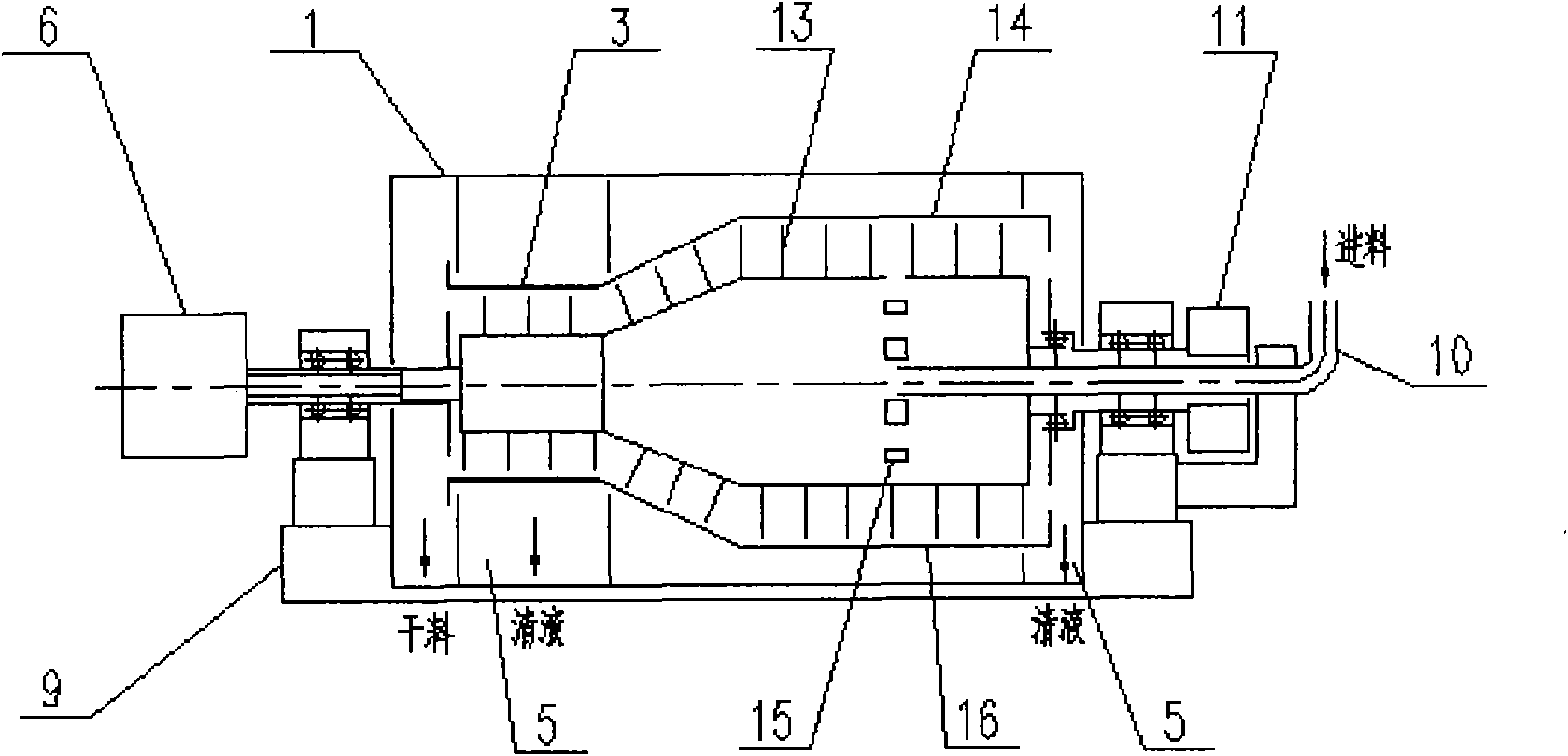
The above-mentioned second type of sedimentation filter centrifuge is mainly used for dehydration of materials with a particle size below 0.5mm. Because the materials are finer and dehydrated mainly by the principle of sedimentation, a higher centrifugal factor is required, so the wear of the screw 13 and the outer drum 14 is more serious. Poor dehydration effect, low output, high energy consumption, high equipment manufacturing cost

Method used


Image

  • Vertical centrifugal hydroextractor
  • Vertical centrifugal hydroextractor
  • Vertical centrifugal hydroextractor

Examples


Embodiment Construction

[0033] According to the present invention Figure 4 to Figure 7 According to the technical solution, the casing 1 and the differential gear 6 are respectively fixed on the base 9, and the output shaft of the differential gear 6 is an inner output shaft 7 and an outer output shaft 8 which are set together, and inner rotors 21 are respectively installed on the upper ends of the inner and outer output shafts. And the outer rotor 22, the upper and lower journals of the sieve plate 20 are rotationally connected with the outer rotor 22 through bearings, and the inner and outer rotors are established by a pin wheel rotation mechanism composed of a pin wheel 18 and a gear 19 (an incomplete gear transmission mechanism can also be used). Drive connection. When the machine is working, the motor drives the differential 6 to drive the inner and outer rotors to rotate at a differential speed through its inner output shaft 7 and outer output shaft 8, and the material is distributed from the ...


PUM


Abstract

The invention discloses a vertical centrifugal hydroextractor, which is used for solid-liquid separation operation in the fields of coal dressing, ore dressing, chemical industry and the like. The vertical centrifugal hydroextractor mainly comprises a housing, a base, an inner rotor, an outer rotor, screen plates, a pin gear drive device, a differential and the like, wherein the outer rotor is equally divided into a plurality of fan-shaped chambers along a circumference; each fan-shaped chamber is provided with a corresponding screen plate which can rotate around an axis of the fan-shaped chamber; the inner rotor consists of a feeding trough, a batching cylinder and a batching trough; the inner rotor and the outer rotor are arranged on an input shaft and an output shaft of the differential respectively; the inner rotor, the outer rotor and the screen plates are in transmission connection through a pin gear drive mechanism; a motor drives the inner rotor and the outer rotor to rotate in a differential way through the differential; materials are delivered from the inner rotor to the outer rotor and subjected to dehydration and dying under the action of centrifugal force; the pin gear drive mechanism controls the screen plates to rotate; and filter cakes are removed by using centrifugal force. The centrifugal hydroextractor has the advantages of fundamentally solving the problem of severe wear, prolonging the service life of parts, such as the screen plates and the like, and saving energy consumption.

Description

technical field [0001] The invention relates to a vertical centrifugal dehydrator, which is a device for solid-liquid separation by centrifugal force, and is mainly used in coal preparation, mineral processing, chemical industry and other industries, such as clean coal, coal slime water, various pulp, alumina, etc. Solid-liquid separation operations. Background technique [0002] Among the various industries mentioned above, the dehydration equipment using the centrifugal method is the most widely used, because this type of equipment has the advantages of high production capacity, good dehydration effect, low energy consumption, less equipment investment, and small footprint. [0003] In the coal preparation industry, the first type of centrifugal dehydration equipment has two types of centrifugal dewatering machines: scraper unloading and vibrating unloading, and also vertical and horizontal. figure 1 It is a schematic diagram of a scraper unloading vertical centrifugal de...

Claims


Application Information

Patent Timeline
IPC IPC(8): F26B5/08
CPCY02P20/10
Inventor 张学骞
Owner 张学骞
Learn More