Piezoresistive sensor circuit capable of automatically correcting zero-bias

A sensor circuit and automatic correction technology, applied in the direction of instruments, etc., can solve the problems of difficulty in guaranteeing capacitance, automatic correction circuit not suitable for piezoresistive sensors, inconvenience in use, etc.

Inactive Publication Date: 2010-08-18
HARBIN INST OF TECH
View PDF0 Cites 20 Cited by
  • Summary
  • Abstract
  • Description
  • Claims
  • Application Information

AI Technical Summary

Problems solved by technology

[0004] Existing solutions generally rely on manual adjustment, which wastes manpower and material resources. After manual adjustment, because the adjustable potentiometer will shift to a certain extent over time, it generally takes time to adjust, and there are many problems in use. in...

Method used


Image

  • Piezoresistive sensor circuit capable of automatically correcting zero-bias
  • Piezoresistive sensor circuit capable of automatically correcting zero-bias
  • Piezoresistive sensor circuit capable of automatically correcting zero-bias

Examples


Embodiment Construction

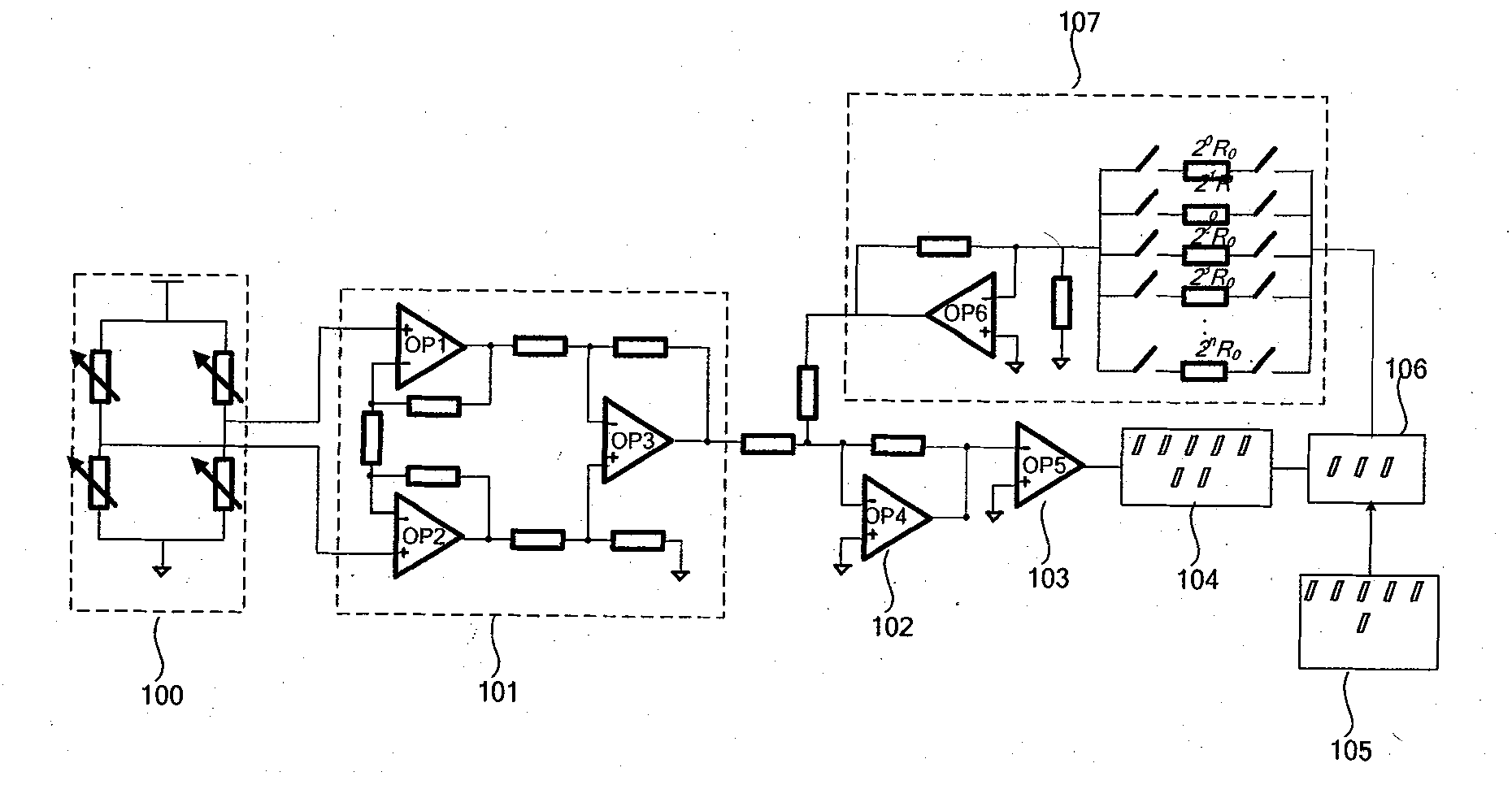
[0013] figure 1 A schematic diagram showing the circuit structure of the piezoresistive sensor with automatic zero point offset correction in this embodiment.

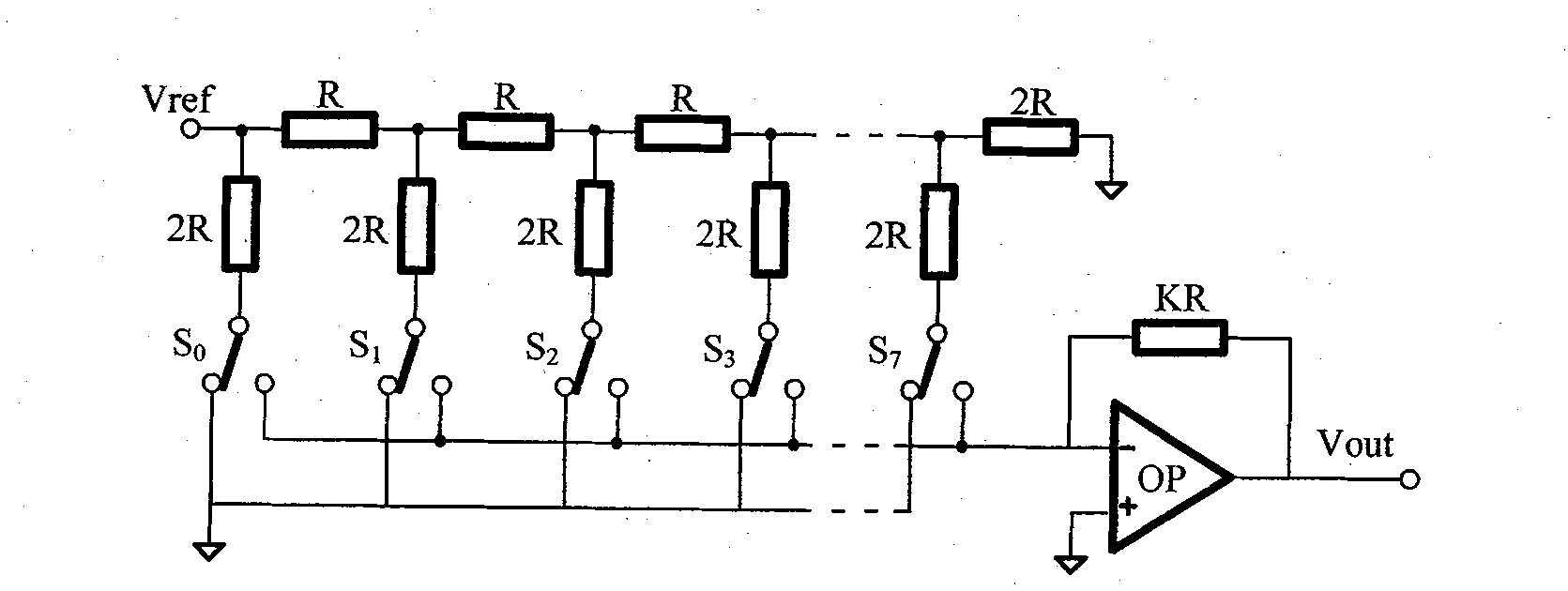
[0014] Such as figure 1 As shown, the interface circuit has: instrumentation amplifier part (101), subtractor part (102), comparator part (103), bidirectional reversible counter part (104), start control unit part (105), latch part ( 106), D / A converter part (107), subtractor part (108).

[0015] The instrument amplifier part (101) amplifies the differential mode voltage output by the piezoresistive sensor structure (100), which includes the zero point offset voltage of the piezoresistive sensor structure (100) caused by asymmetry, differential mode voltage and D / A conversion The correction voltage output by the device part (107) is output through the subtractor part (102), and the output result of the subtractor part (102) is compared with the center potential through the comparator part (103), and the output result...


PUM


Abstract

The invention provides a piezoresistive sensor circuit capable of automatically correcting zero-bias. The invention provides an interface circuit capable of automatically correcting the zero point bias voltage of a piezoresistive sensor so that the measuring results can be more precise. When a piezoresistive sensor system is electrified, a successive approximation principle is utilized for automatically correcting the output of the piezoresistive sensor system, the unchanged correction voltage can be maintained for a long time, and in addition, the time drift problem does not exist. The invention overcomes the defects of the existing piezoresistive sensor circuit, and has the characteristic of automatically correcting the output voltage of the sensor.

Description

(1) Technical field [0001] The invention belongs to the field of sensor interface circuits, in particular to piezoresistive sensor circuits. (2) Background technology [0002] The rapid development of sensor technology, behind which the huge market demand is the main driving force for development. The piezoresistive sensor is a sensor with a simple structure and a wide range of applications. From automobiles and consumer electronics in the civilian field to the military field, piezo-positive sensors play an important role in it. Therefore, with the expansion and deepening of the application of piezoresistive sensors in various fields, while improving performance, the accuracy of piezoresistive sensors should be guaranteed. For example, piezoresistive sensors inevitably have some errors in the production process, so that The output deviation is generated, and the automatic correction zero offset function of the piezoresistive sensor circuit can provide more accurate correct...

Claims


Application Information

Patent Timeline
IPC IPC(8): G01D18/00
Inventor 刘晓为董长春尹亮陈伟平刘云涛付强
Owner HARBIN INST OF TECH
Why Eureka
Try Eureka