
Photoelectric combined submarine power cable

A submarine power cable and photoelectric composite technology, which is applied in the direction of submarine cables, power cables with shielding layer/conductive layer, communication cables, etc., can solve the problems of insufficient tensile strength, high production cost, high copper price, etc., and achieve cost saving , the effect of reducing production costs

Active Publication Date: 2012-08-22
ZHOUSHAN ELECTRIC POWER SUPPLY COMPANY OF STATE GRID ZHEJIANG ELECTRIC POWER +1
View PDF6 Cites 0 Cited by
  • Summary
  • Abstract
  • Description
  • Claims
  • Application Information

AI Technical Summary

Problems solved by technology

But its disadvantage is that the conductor has not been improved. Most of the conductors of this cable are made of copper, because copper not only satisfies good electrical conductivity, but also meets the requirement that the cable has sufficient tensile strength, but because of the high price of copper, the production cost is relatively high. , and the use of other materials has insufficient tensile strength, so it has become a development trend to develop a submarine cable that can satisfy both good electrical conductivity and sufficient tensile strength.

Method used


Image

  • Photoelectric combined submarine power cable
  • Photoelectric combined submarine power cable
  • Photoelectric combined submarine power cable

Examples


Embodiment Construction

[0018] The present invention will be further described in detail below in conjunction with the accompanying drawings and embodiments.

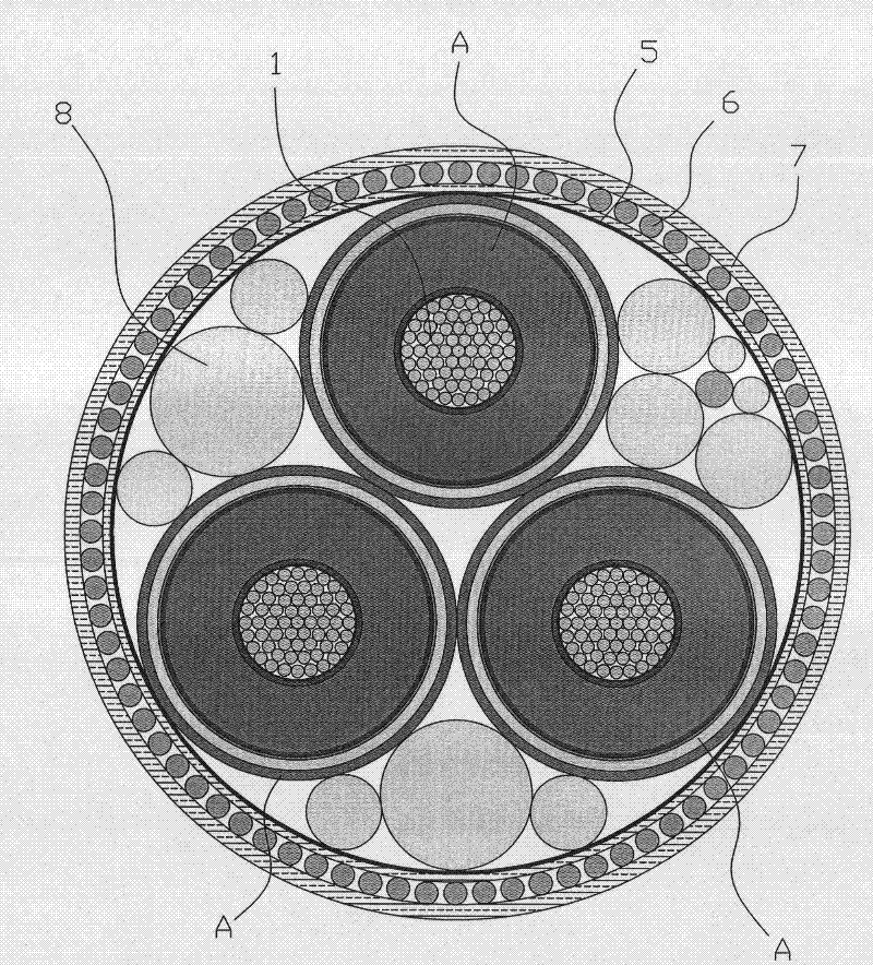
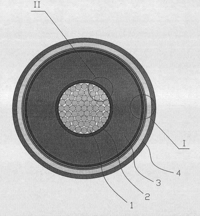
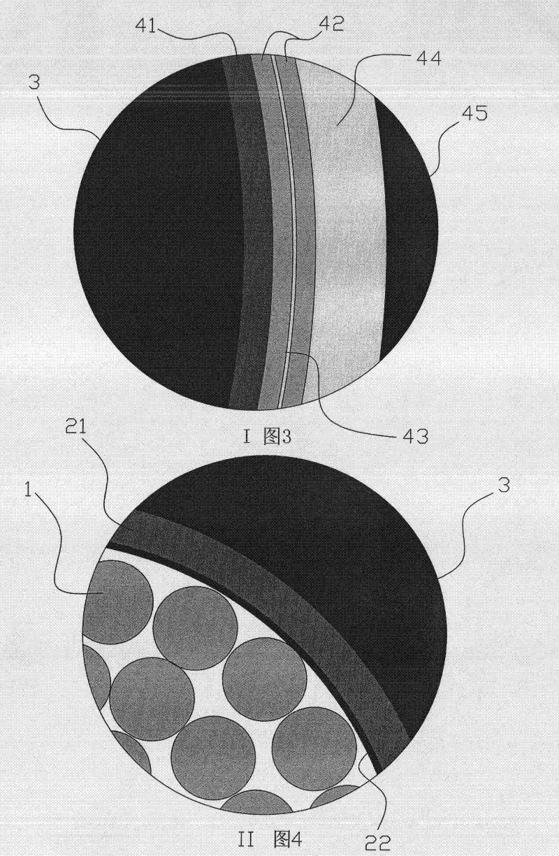
[0019] Such as figure 1 , image 3 , Figure 4 and Figure 5 As shown, the photoelectric composite submarine power cable of the present embodiment includes a wire core 1, a shielding layer 2, an insulating layer 3, an insulator shielding layer and an inner sheath 4, an armored inner cushion layer 5, an armored layer 6 and an armored The outer protective layer 7, the fiber unit A formed by the core 1, the shielding layer 2, the insulating layer 3, the insulator shielding layer and the inner sheath 4 are sequentially arranged from the inside to the outside. The fiber unit A has three groups and is stacked on top of each other. Put together, the armored inner cushion layer 5, the armored layer 6 and the armored outer protective layer 7 wrap the three groups of optical fiber units A in order from the inside to the outside, and the three groups ...


PUM


Abstract

The invention relates to a photoelectric combined submarine power cable which comprises a cable core (1), a shielding layer (2), an insulating layer (3), an insulator shielding layer and internal protecting layer (4), an armored inner liner layer (5), an armored layer (6) and an armored outer protective layer (7). An optical fiber unit (A) is formed by sequentially arranging the cable core (1), the shielding layer (2), the insulating layer (3) and the insulator shielding layer and internal protecting layer (4) from interior to exterior, and three groups of optical fiber units (A) are mutuallystacked together. The photoelectric combined submarine power cable is characterized in that the cable core (1) comprises a steel wire lead and an aluminum lead, wherein the steel wire lead is arranged in the center of the aluminum lead, and the steel wire lead and the aluminum lead are jointly twisted into the cable core (1) in a steel core aluminum twisted wire structure. Compared with the priorart, the structure has the advantages that the cost is saved by substituting aluminum for copper, the conductivity fully meets the standard, and the twisted wire of the steel wire lead and the aluminum lead can solve the problem of poor tensile strength of the aluminum lead. The power cable has decreased production cost and has the conductivity and the tensile strength both meeting the stipulatedstandard.

Description

technical field [0001] The invention relates to the technical field of submarine cables, in particular to a submarine power cable of submarine photoelectric composite. Background technique [0002] An existing Chinese utility model patent with the patent number CN200820034047.X titled "Submarine Optical Fiber Composite Power Cable" discloses a structure, which includes a conductor, an insulating layer, a water blocking layer, a metal sheath layer, and an inner sheath layer , inner cushion layer, outer sheath layer, armor layer, and outer layer, an insulating layer is arranged outside the conductor, a water-blocking layer is arranged outside the insulating layer, a metal sheath layer is arranged outside the water-blocking layer, and a metal sheath layer is arranged outside the water-blocking layer. There is an inner sheath layer outside the sheath layer; the outermost layer of the submarine power cable is an outer sheath layer, and an armor layer is installed inside the outer...

Claims


Application Information

Patent Timeline
Patent Type & Authority Patents(China)
IPC IPC(8): H01B11/22H01B7/14H01B9/02H01B5/10
Inventor 毛南平黄启李懿何旭涛郑新龙郁单沈丁向楠
Owner ZHOUSHAN ELECTRIC POWER SUPPLY COMPANY OF STATE GRID ZHEJIANG ELECTRIC POWER
Learn More