Three-terminal modulator for lower-frequency modulating type radiometer receiver

A low-frequency modulation and modulation radiation technology, applied in the field of three-terminal modulators, which can solve the problems of wear and tear of the modulated square wave speed, slow response speed, and increased system gain instability.

Inactive Publication Date: 2010-08-18
南京紫淮矿用电子高科技有限公司 +2
View PDF0 Cites 6 Cited by
  • Summary
  • Abstract
  • Description
  • Claims
  • Application Information

AI Technical Summary

Problems solved by technology

The most critical thing in the added modulation-phase detection system is a three-port modulator with low insertion loss, low noise and high reverse rejection, because both the insertion loss and the modulator's own noise will increase the noise of the radio radiation receiving system and Increase the gain instability of the system
[0003] In microwave and millimeter wave radio astronomy radiation receiving systems, waveguide or coaxial electronically controlled ferrite circulators are usually used. The insertion loss is between 0.1 and 1db, and the reverse suppression is ≥20db. Since the ferrite device itself does not It does not produce electronic noise, but when it comes to medium wave, long wave, especially the ultra-long wave band below 100KHz, it is very difficult to find a three-port modulator with low insertion loss, low noise and high reverse rejection
Modulators made of transistors and field effect tubes will introduce noise, and the insertion loss is not easy to make very small; using electromagnetic strip line switch, the response speed is slow and cannot keep up with the modulation square wave speed, and there is wear and tear
Therefore, a three-port modulator with low insertion loss, low noise and high reverse suppression that can work well in the high-sensitivity Dicke-type modulated radio radiation receiving system of 100Hz-10MHz is difficult to solve

Method used


Image

  • Three-terminal modulator for lower-frequency modulating type radiometer receiver
  • Three-terminal modulator for lower-frequency modulating type radiometer receiver
  • Three-terminal modulator for lower-frequency modulating type radiometer receiver

Examples


Embodiment Construction

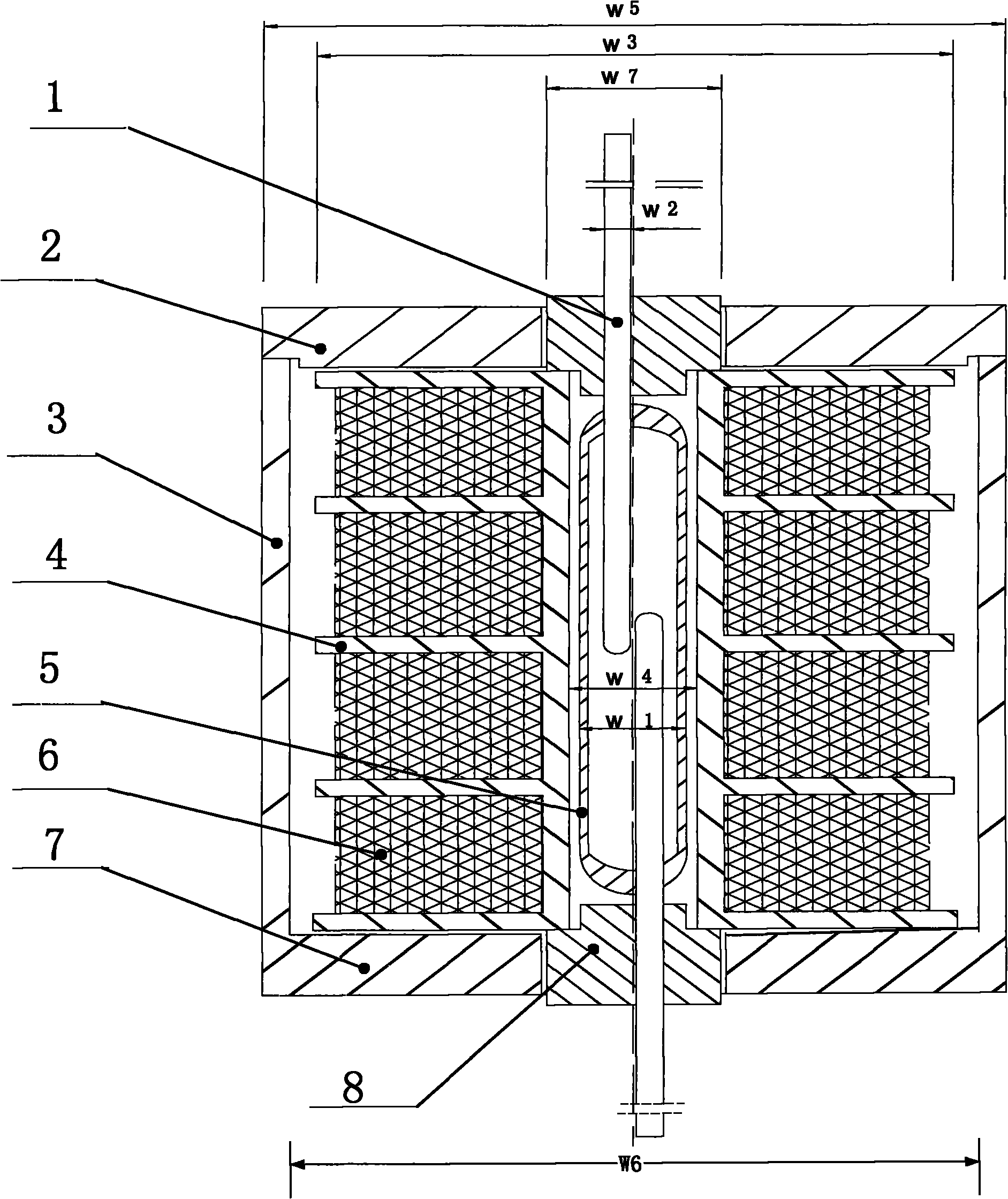
[0022] figure 1 It is the mechanical structure diagram of the coaxial transmission line miniature dry reed switch switch designed and manufactured by us, and its structure size has been strictly designed and calculated. 5 is a miniature reed switch, which adopts the garden tube type ORD-219 of Japan OKI Company, and its size W1 is Φ2×12; 1 is the double-ended outer lead of the miniature reed switch, and the size W2 is about Φ0.5×16; The 4-hole coil tube made of low dielectric loss plastic rod lathing, its outer diameter W3 is Φ12×13, its inner diameter W4 is Φ2.4×13; The outer diameter W5 is Φ14×16.4, the inner diameter W6 is Φ13×14, and the wall thickness of the whole body is 0.5mm; 2 is the end cap of the electric pure iron hollow cup, which is also made of electric pure iron rod lathe, which is similar to the electric pure iron hollow cup. The inner edge of the cup is a transitional fit; 8 is a polyethylene ring with a Φ0.5 hole in the middle filled in the Φ3.3 openings at...


PUM


Abstract

The invention relates to a three-terminal modulator for a lower-frequency modulating type radiometer receiver, which is based on a Dicke type modulating receiving system. The three-terminal modulator for the lower-frequency modulating type radiometer receiver is characterized in that the input end of the Dicke type modulating receiving system is provided with the three-terminal modulator, three ports are respectively connected with an antenna, a terminal load and an electronic receiving front end input port, wherein the electronic receiving front end input port is continuously switched between the antenna and the terminal load with a certain frequency. The three-terminal modulator adopts a fast response electromagnetic switch consisting of a reed pipe, a magnet coil and a tubular magneticshielding outer cover as a basic switching unit, a relay inductive load drive integrated circuit comprising a biasing resistor and a negative peak restrain diode as a basic breakover control unit anda CMOS (Complementary Metal Oxide Semiconductor) circuit which is controlled by modulating square signals output by a low-frequency system of the Dicke type modulating electric radiation receiver as a double-phase control voltage generating unit.

Description

technical field [0001] The invention belongs to the field of radio radiation receiving in radio astronomy, in particular to a three-terminal modulator used for a low-frequency modulation radiometer receiver. Background technique [0002] In the radio astronomy total intensity radiometer receiving equipment, high gain stability is the first and necessary requirement, because the radio radiation of celestial bodies is a radiation in the form of white noise, and if it satisfies the Gaussian distribution, it is essentially the same as The electronic noise generated by the radio radiation receiving system itself is not different. Therefore, if the gain of the radio radiation receiving system is unstable, when the output of the radio radiation receiving system changes, we cannot distinguish whether the radio radiation receiving system received the noise from the celestial body itself. The variation of the radio radiation signal is also the variation of the local electronic noise o...

Claims


Application Information

Patent Timeline
Patent Type & Authority Applications(China)
IPC IPC(8): H04B1/16
Inventor 黄福泉袁亮葛连生倪玉安高宇红柏发松
Owner 南京紫淮矿用电子高科技有限公司
Why Eureka
Try Eureka