Rolling control method of high-strength cold rolled steel strip
A cold-rolled strip steel and control method technology, applied in metal rolling, profile control, metal rolling, etc., can solve problems such as short service period of back-up rolls, difficulty in controlling plate shape, large crown of work rolls, etc., and achieve improvement The effect of service cycle, reduction of production cost and reduction of roll consumption
Active Publication Date: 2010-08-25
BAOSHAN IRON & STEEL CO LTD +1
View PDF0 Cites 15 Cited by
- Summary
- Abstract
- Description
- Claims
- Application Information
AI Technical Summary
Problems solved by technology
The purpose of the present invention is to provide a rolling control method for high-strength cold-rolled strip steel, so as to solve the problem that the existing high-strength steel with 600 MPa and above is cold-rolled. Defects, high roll consumption and short service life of backup rolls, so as to enhance the shape control ability of ordinary cold rolling mills to obtain high-strength steel with good shape, and provide a basis for stable plate passing in the post-rolling process
Method used
View moreImage
Smart ImageViewing Examples
Examples
Embodiment Construction
Login to View More PUM
 Abstract
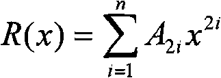
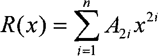
The invention discloses a rolling control method of a high-strength cold rolled steel strip. A supporting roll with a combined roll forming curve is used in the rolling process. The combined roll forming curve comprises a middle curve and two linear chamfer angles, wherein the middle curve is arranged in the middle of the combined roll forming curve; the two linear chamfer angles are respectively arranged on two sides of the middle curve symmetrically; the widths of the two linear chamber angles are both 50-10 mm; and the heights of the two linear chamber angles are both 0.5-1.5 mm. The rolling control method has simple operation, convenient processing of the supporting roll and low cost. By adopting the method, the transverse rigidity of a supporting roll gap can be improved, the plate shape control capability of common cold-rolling mills is enhanced to obtain a favorable high-strength steel plate shape, and foundation is provided for stabilizing a through plate in the steps after rolling. Simultaneously, the method can further effectively reduce the roll consumption and prolong the service life of rolls. Therefore, the production cost is obviously reduced, and the popularization prospect and the application prospect are favorable.
Description
technical field The invention relates to a method for controlling the shape of cold-rolled strip steel, in particular to a method for controlling the rolling of high-strength cold-rolled strip steel whose strength reaches 600 MPa and above and whose shape is difficult to control. Background technique A large number of cold-rolled strips are required in industries such as automobiles and construction, and based on the consideration of weight reduction, energy saving, and cost reduction, they also increasingly require the use of thinner steel sheets, which puts more demands on the mechanical properties of strip steel. high demands. In order to ensure the safety in use, the current high-strength steel is gradually developing in the direction of thin gauge and high strength, so the problem of plate shape has become increasingly prominent. Due to the high yield limit of high-strength steel, this means that during continuous cold rolling, each stand of the cold rolling mill shou...
Claims
Login to View More Application Information
Patent Timeline
 IPC IPC(8): B21B37/30B21B29/00B21B27/02
Inventor 路凤智张清东吴彬姜正连饶志雄邹美平杨凯夫柯重建
Owner BAOSHAN IRON & STEEL CO LTD
Features
- R&D
- Intellectual Property
- Life Sciences
- Materials
- Tech Scout
- Unparalleled Data Quality
- Higher Quality Content
- 60% Fewer Hallucinations
Learn More Browse by: Latest US Patents, China's latest patents, Technical Efficacy Thesaurus, Application Domain, Technology Topic, Popular Technical Reports.
© 2025 PatSnap. All rights reserved.Legal|Privacy policy|Modern Slavery Act Transparency Statement|Sitemap|About US| Contact US: help@patsnap.com


