High pressure resistant and impact resistant roller bit with high rotating speed

A roller cone bit, high-pressure-resistant technology, applied in the direction of drill bits, drilling equipment, earthwork drilling, etc., can solve the problem of reducing the contact area between the large journal 41 of the tooth palm and the large shaft hole 21 of the cone, poor impact resistance, no Locking function and other issues to achieve the effect of reducing overload, improving lubrication conditions, and increasing the bearing capacity of rollers

Inactive Publication Date: 2010-08-25
TIANJIN LILIN BIT
View PDF4 Cites 5 Cited by
  • Summary
  • Abstract
  • Description
  • Claims
  • Application Information

AI Technical Summary

Problems solved by technology

As shown in the figure, an annular raceway 90 is provided around the inner wall of the large shaft hole 21 of the cone, and the large journal 41 of the tooth palm is a smooth cylindrical surface without an annular raceway, so a circle of cylindrical rollers in the raceway 50 just changes sliding friction into rolling friction, which solves the sliding wear problem of sliding friction. It is suitable for high speed, but it has no locking function. The technical defects brought by this rolling bearing structure are: (1) due to the large journal 41 end Locking ball 6 is arranged on the top, so a certain space is occupied, the length of cylindrical roller 50 is limited, and the length of existing cylindrical roller is generally less than 20mm; (2) cylindrical roller 50 reduces the tooth palm The contact area between the large journal 41 and the large shaft hole 21 of the cone; (3) the two ends of the cylindrical roller 50 are planes, and the sharp edges of the end surfaces are prone to stress concentration; The structure of the drill bit is resistant to high pressure and has poor impact resistance, so it is not suitable for high-pressure deep well drilling operations

Method used


Image

  • High pressure resistant and impact resistant roller bit with high rotating speed
  • High pressure resistant and impact resistant roller bit with high rotating speed
  • High pressure resistant and impact resistant roller bit with high rotating speed

Examples


Embodiment Construction

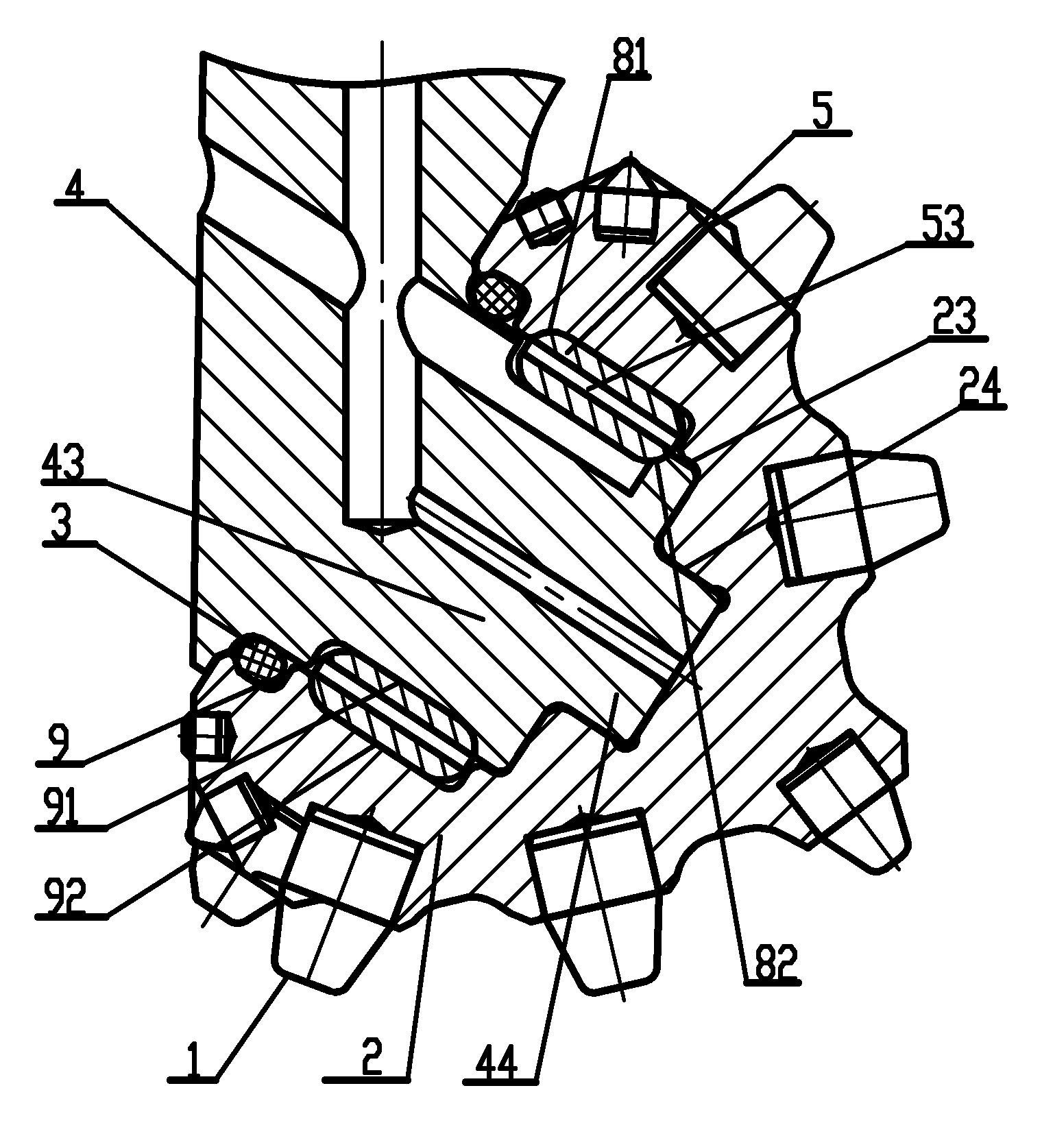
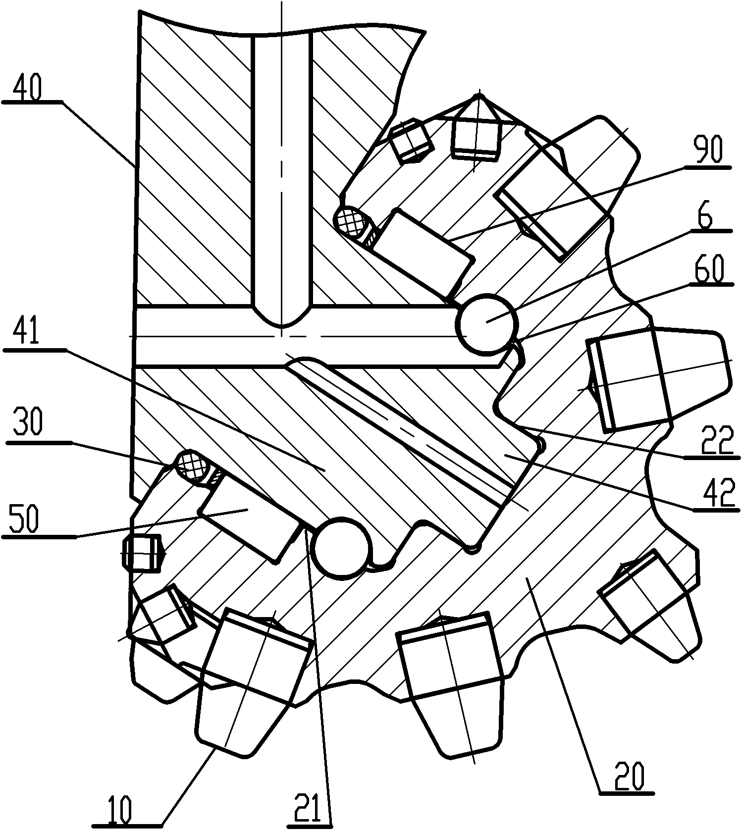
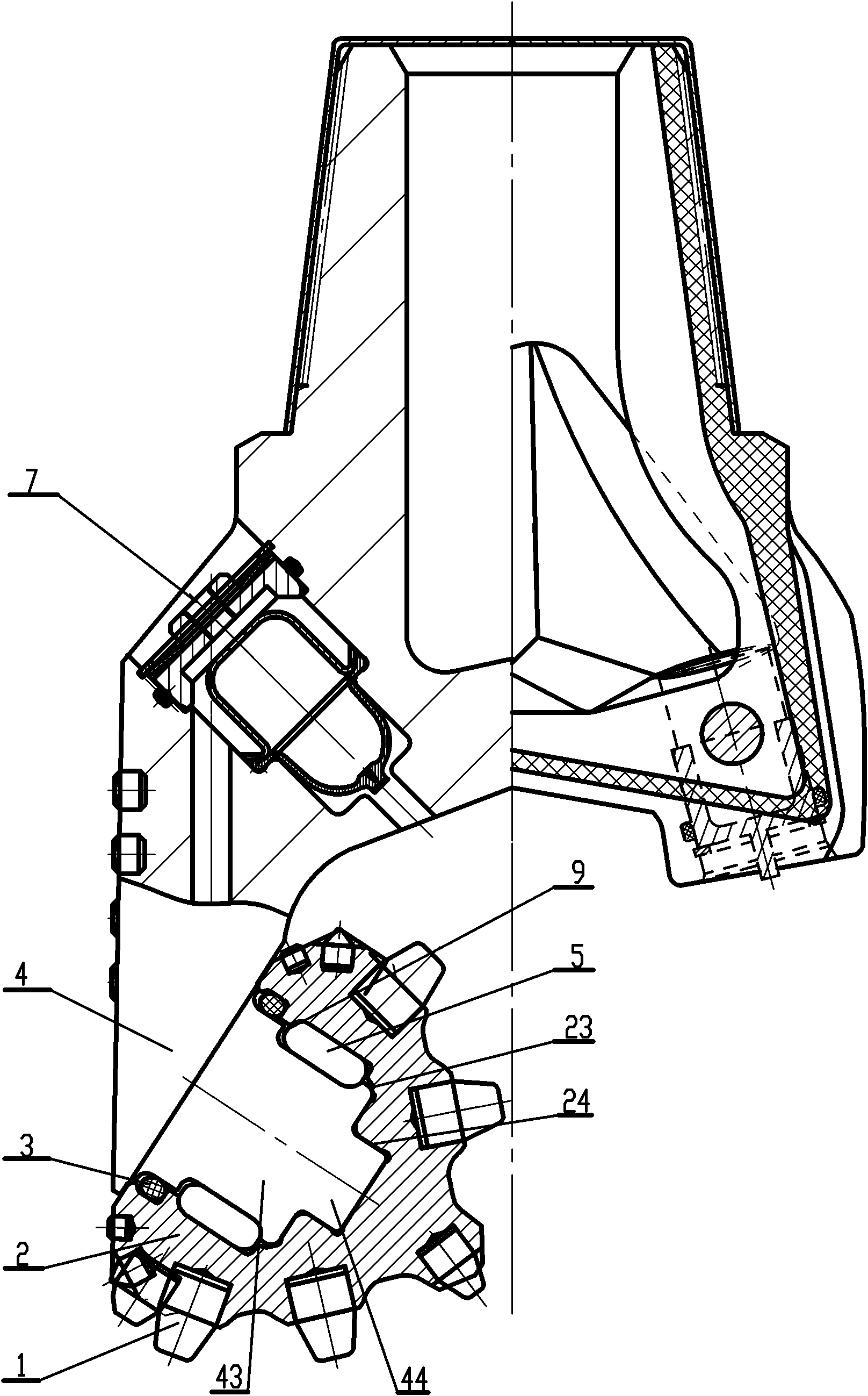
[0019] Figures 2 to 4 show a high-speed impact-resistant roller cone bit, including a cone 2 inlaid with an alloy tooth 1, a tooth palm 4, and the tooth palm 4 is provided with a large journal 43 and a small journal 44, and the cone 2 The large shaft hole 23 and the small shaft hole 24 are correspondingly provided. The large shaft hole 23 and the small shaft hole 24 of the cone are respectively set on the large journal 43 and the small journal 44 of the tooth palm, and are embedded in the raceway 9 The roller 5 in the middle is in rolling friction connection with the tooth palm 4, and the tooth palm 4 is also provided with an oil supply system 7 and a rubber sealing ring 3.

[0020] As shown in Fig. 2 and Fig. 3, the present invention is characterized in that the outer surface of the above-mentioned large journal 43 is provided with a journal half formed by a journal ring-shaped groove whose width extends to the end of the large journal 43. The raceway 91 is provided with a sh...


PUM


Abstract

The invention relates to a high pressure resistant and impact resistant roller bit with high rotating speed, comprising a roller cone and a cone leg. The cone leg is provided with a big journal and a small journal, and the roller cone is correspondingly provided with a big axle hole and a small axle hole which are respectively sleeved on the big journal and the small journal of the cone leg and connected to the cone leg in rolling friction through a pin roller embedded into a ball track. The roller bit is characterized in that the periphery of an outer surface of the big journal is provided with a journal semi-ball track formed by a journal annular groove with a width extended nearby the end part of the big journal, the wall of the big axle hole and the journal semi-ball track are correspondingly provided with an axle hole semi-ball track formed by an axle hole annular groove, the ball track is formed by closing the journal semi-ball track and the axle hole semi-ball track, the pin roller is a cavity lengthening-type pin roller with an end face as a curved surface, and a generator of a cylindrical surface of the pin roller is a convex log curve or a camber line. The invention has the advantages of carrying more loads and improving the impact resistant toughness and is suitable for the high pressure deep drilling operation.

Description

technical field [0001] The invention relates to a roller cone bit used for oilfield drilling and geological exploration, in particular to a high-speed, high-pressure, impact-resistant roller cone bit. Background technique [0002] At present, roller cone bits are widely used in the field of oilfield drilling and geological exploration. As shown in FIG. 1 , the roller cone bit is mainly composed of a roller cone 20 and a tooth palm 40. The roller cone 20 is connected to the tooth palm through a sliding bearing or a rolling bearing structure. The palm 40 is provided with a large journal 41 and a small journal 42, and the cone 20 is correspondingly provided with a large shaft hole 21 and a small shaft hole 22, and the large shaft hole 21 and the small shaft hole 22 of the cone are respectively sleeved on the large On the journal 41 and the small journal 42 , the cone 20 is locked on the large journal 41 , that is, on the tooth palm 40 , by a circle of ring shaft locking balls 6...

Claims


Application Information

Patent Timeline
Patent Type & Authority Applications(China)
IPC IPC(8): E21B10/22F16C33/34
Inventor 薛中学
Owner TIANJIN LILIN BIT
Why Eureka
Try Eureka