Electromagnetic pulse rigid shaft sliding valve

An electromagnetic pulse, rigid shaft technology, applied in the direction of valve details, valve devices, engine components, etc., can solve the problems of large volume of electromagnetic pulse valve, large valve installation distance, affecting the quality of valves, etc., and achieve stable and reliable performance and coaxiality Good, easy to create effects

Inactive Publication Date: 2010-08-25
XIECHANG ENVIRONMENTAL PROTECTION TECH CO LTD
View PDF8 Cites 4 Cited by
  • Summary
  • Abstract
  • Description
  • Claims
  • Application Information

AI Technical Summary

Problems solved by technology

[0002] The electromagnetic pulse valve (air flow valve) is the core component of the dust removal system of the bag filter. It is mainly composed of valve body, pilot control device, diaphragm assembly, spring and other components. The diaphragm assembly and spring of the working chamber are The most important element that determines the performance and life of the valve, because they are in high-pressure, high-frequency reciprocating motion for a long time, long-term work will cause the diaphragm of the diaphragm assembly to rupture, and the rubber support of the diaphragm assembly will be damaged and aged , spring breakage and other fatal defects seriously affect the quality of the valve
At the same time, the volume of the conventional electromagnetic pulse valve is large, which leads to a large installation distance of the valve, which makes the arrangement of the injection pipe less selective when designing the injection system of the bag filter.

Method used


Image

  • Electromagnetic pulse rigid shaft sliding valve
  • Electromagnetic pulse rigid shaft sliding valve
  • Electromagnetic pulse rigid shaft sliding valve

Examples


Embodiment Construction

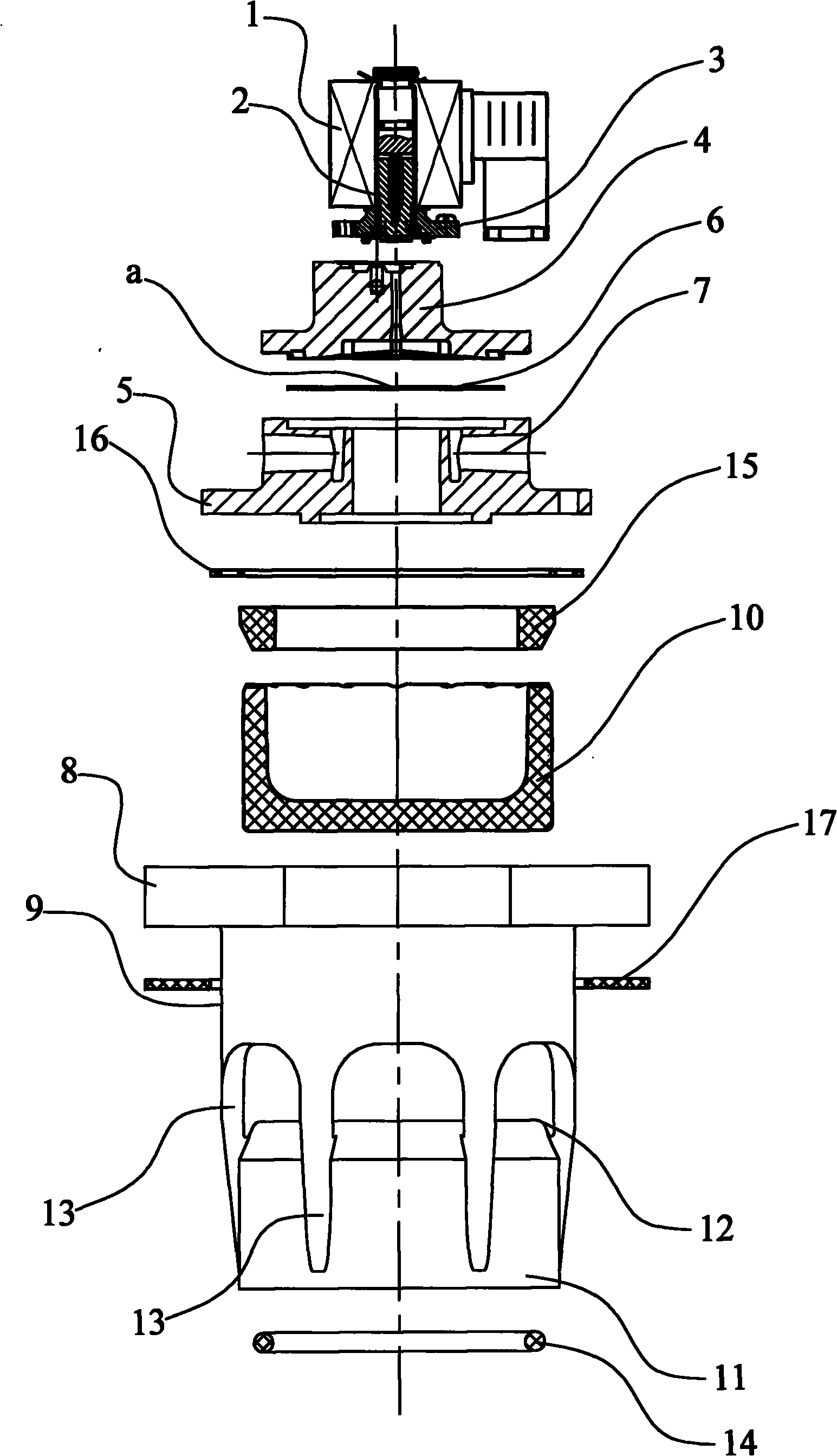
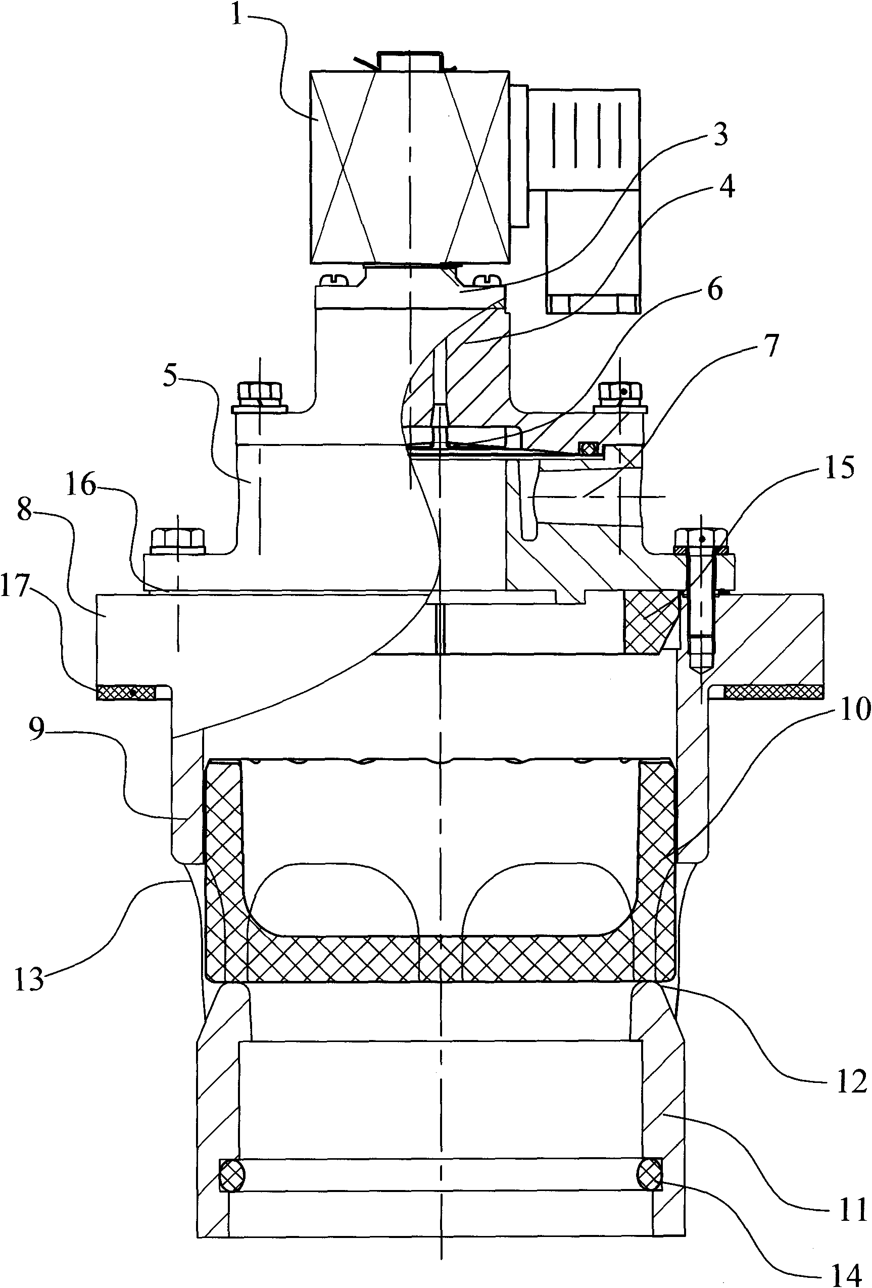
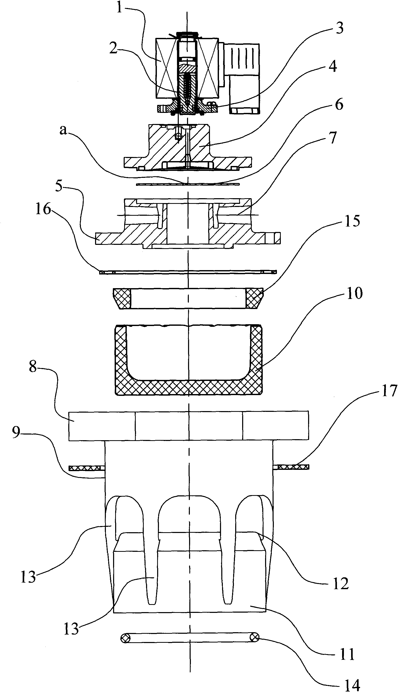
[0023] Fig. 1 is a schematic structural diagram of the present invention, and Fig. 2 is a schematic diagram of an exploded structure of Fig. 1, as shown in Fig. Pilot head pressure plate 3, pilot seat 4, valve cover 5, flexible diaphragm 6 is installed in the valve cover 5, and there is a damping hole a in the flexible diaphragm (the center of the flexible diaphragm at the damping hole, the area ratio relationship between the damping hole and the flexible diaphragm is 1:550~1:5500), the bonnet 5 has an unloading hole 7, the bonnet 5 is connected with a valve seat 8, the valve seat 8 has a central through hole, and the central through hole extends downward to form a sleeve 9 , The sleeve 9 is provided with a bowl-shaped rigid shaft 10 whose cross-section is H-shaped.

[0024] An exhaust outlet connecting pipe 11 is connected under the sleeve 9 of the valve seat 8 , and the bowl-shaped rigid shaft 10 is placed on the top surface 12 of the exhaust outlet connecting pipe 11 . The...


PUM


Abstract

The invention discloses an electromagnetic pulse rigid shaft sliding valve which comprises a pilot head component, a pilot head pressure plate, a pilot base and a valve cover. The pilot head component is controlled by an electromagnetic coil, the pilot head pressure plate, the pilot base and the valve cover are sequentially connected, a flexible diaphragm is mounted in the valve cover and internally provided with a damping hole, balance holes are arranged on the valve cover, a valve seat is connected with the lower part of the valve cover and provided with a central through hole which extends downwards to form a sleeve, the sleeve is internally provided with a bowl-shaped rigid shaft with a U-shaped section, the lower part of the valve seat sleeve is connected with an air vent connecting tube; and the bowl-shaped rigid shaft is arranged on the top end surface of the air vent connecting tube. The bowl-shaped rigid shaft substitutes for a diaphragm component of a diaphragm-type electromagnetic pulse valve working cavity in the electromagnetic pulse rigid shaft sliding valve to save a pressure spring on the diaphragm and greatly prolong the service life of the electromagnetic pulse valve; in addition, by adopting the circular end surface in a closing and start-type bowl-shaped rigid shaft structure, the electromagnetic pulse rigid shaft sliding valve has easy manufacture and reliable working performance; moreover, the electromagnetic pulse rigid shaft sliding valve has stronger pulse blowing performance and less mounting distance. Blowing tubes are better arranged when a bag-type dust collector blowing system is designed.

Description

technical field [0001] The invention relates to the field of dust cleaning system of bag type dust collector, in particular, the invention relates to an electromagnetic pulse rigid shaft sliding valve. Background technique [0002] The electromagnetic pulse valve (air flow valve) is the core component of the dust removal system of the bag filter. It is mainly composed of valve body, pilot control device, diaphragm assembly, spring and other components. The diaphragm assembly and spring of the working chamber are The most important element that determines the performance and life of the valve, because they are in high-pressure, high-frequency reciprocating motion for a long time, long-term work will cause the diaphragm of the diaphragm assembly to rupture, and the rubber support of the diaphragm assembly will be damaged and aged , spring breakage and other fatal defects seriously affect the quality of the valve. At the same time, the volume of the conventional electromagneti...

Claims


Application Information

Patent Timeline
Patent Type & Authority Applications(China)
IPC IPC(8): F16K31/06F16K31/122F16K31/126
Inventor 刘建华鲁华火齐学超陆亚萍江加辉
Owner XIECHANG ENVIRONMENTAL PROTECTION TECH CO LTD
Why Eureka
Try Eureka