

Method for estimating exhaust enthalpy of low pressure cylinder of steam turbine in real time
A steam turbine and exhaust steam enthalpy technology, which is applied in the direction of engine testing, machine/structural component testing, measuring devices, etc., can solve the problems that the loop iterative algorithm cannot converge, and the calculation speed cannot meet the needs of online monitoring of the unit, etc.
Inactive Publication Date: 2010-08-25
NORTH CHINA ELECTRIC POWER UNIV (BAODING)
View PDF2 Cites 33 Cited by
- Summary
- Abstract
- Description
- Claims
- Application Information
AI Technical Summary
Problems solved by technology
Loop iterative algorithms often fail to converge due to various reasons
Even if it can converge, its calculation speed is far from meeting the needs of on-line monitoring of the unit
Method used
View moreImage
Smart ImageViewing Examples

Examples
Embodiment Construction
Login to View More PUM
 Abstract
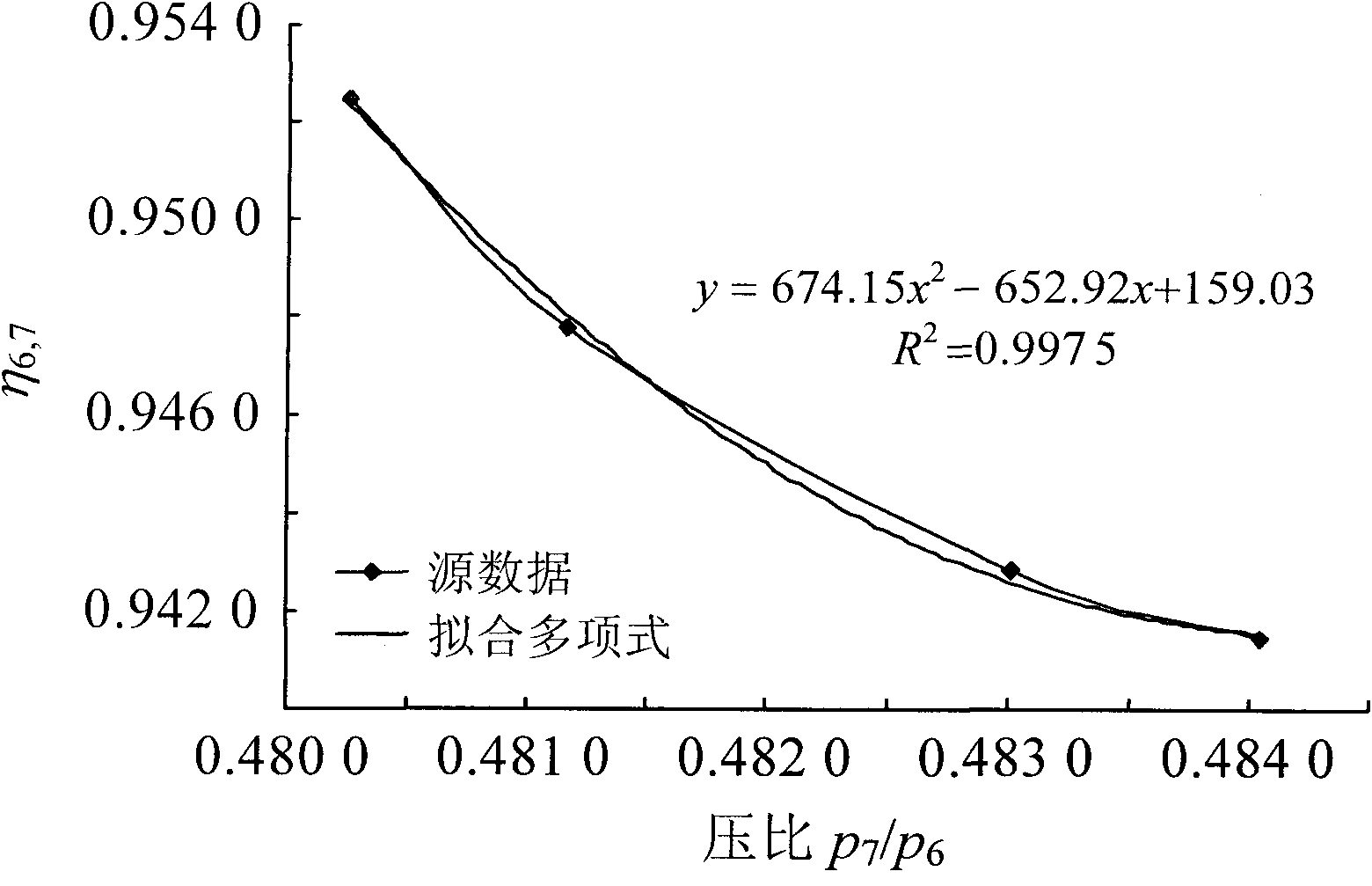
The invention discloses a method for estimating the exhaust enthalpy of a low pressure cylinder of a steam turbine in real time, which belongs to the field of steam turbine parameter measurement. The method comprises: firstly, defining the exhaust efficiency of the (i+1)th stage of a turboset; secondly, obtaining the exhaust enthalpy of the (i+1)th stage of the turboset accordingly; and thirdly, according to a collected heat balance diagram of the steam turbine, obtaining the design parameters of the steam turbine under various working conditions, fitting the relationship between inter-stage efficiency of steam turbine and pressure ratio and calculating the exhaust efficiency eta i, i+1 of the (i+1)th stage of the seam turbine under different conditions from the exhaust efficiency of the last stage upward stage by stage. The method overcomes the drawback that the calculation speed of a loop iteration algorithm is far insufficient for meeting the demands for on-line monitoring of the machine and estimates the exhaust enthalpy of the low pressure cylinder of the steam turbine in real time when the turboset works under various working conditions.
Description
technical field The invention belongs to the field of steam turbine parameter measurement, in particular to a method for real-time estimating the exhaust enthalpy of a low-pressure cylinder of a steam turbine. Background technique During the economical analysis of a steam turbine, it is necessary to determine the thermodynamic state of the final stage of the steam turbine. Under normal working conditions, the steam turbine is in a wet steam state from the last stage of steam extraction to the exhaust steam of the steam turbine. In the wet steam area, pressure and temperature are no longer independent variables, and the dryness parameter of wet steam is needed to determine the state of wet steam. However, the online low-pressure dryness measuring device still has many problems in terms of measurement accuracy, measurement speed, and cost investment. In order to obtain the thermodynamic state of the steam at the tail of the steam turbine online, it is necessary to calculate ...
Claims
Login to View More Application Information
Patent Timeline
 Patent Type & AuthorityApplications(China)
IPC IPC(8): G01M15/00
Inventor曾德良刘吉臻牛玉广王玮张春发
OwnerNORTH CHINA ELECTRIC POWER UNIV (BAODING)