Acid making system suitable for high-concentration sulfur dioxide-containing flue gas

A sulfur dioxide, high-concentration technology, applied in the field of acid production system, can solve the problems of increased investment, increased operating costs, unsuitable for expansion and transformation of flue gas acid production system, and achieves the goal of maintaining heat balance, saving equipment investment and operating costs Effect

Active Publication Date: 2011-06-01
JINLONG COPPER +1
View PDF3 Cites 25 Cited by
  • Summary
  • Abstract
  • Description
  • Claims
  • Application Information

AI Technical Summary

Benefits of technology

This patented technology provides a new way to treat exhaust gases from industrial processes without adding more expensive materials like water misting agents. By incorporating this treatment step beforehand, it reduces sulfur dioxide (SO2) emissions while still producing valuable chemical products such as hydrogen cyclohexane carboxylic acids. Additionally, there are other benefits associated with these technologies including reducing NOX production during combustion reactions, improving fuel efficiency through improved burning performance at low temperatures, lowered CO2 emission levels when used together with nitrogen oxides reduction catalyst systems, resulting in cost savings due to increased power output compared to traditional methods.

Problems solved by technology

This patented technical solution described in the current methods used during manufacturing sulfuric acid involves removing excessive amounts (usually around 15%) from exhaust gases containing harmful substances like nitrogen oxides) before converting them into liquid form through various chemical reactions such as decomposition, neutralization, absorption/adsorption processes. However, these techniques have limitations due to their use at temperatures above 140°C which are common when producing other types of acids without reducing efficiency. Therefore, new solutions must be developed to address issues related to efficient removal of unwanted materials while maintaining safe operation conditions over time.

Method used


Image

  • Acid making system suitable for high-concentration sulfur dioxide-containing flue gas
  • Acid making system suitable for high-concentration sulfur dioxide-containing flue gas
  • Acid making system suitable for high-concentration sulfur dioxide-containing flue gas

Examples


Embodiment Construction

[0021] The present invention will be described in further detail below in conjunction with specific embodiments.

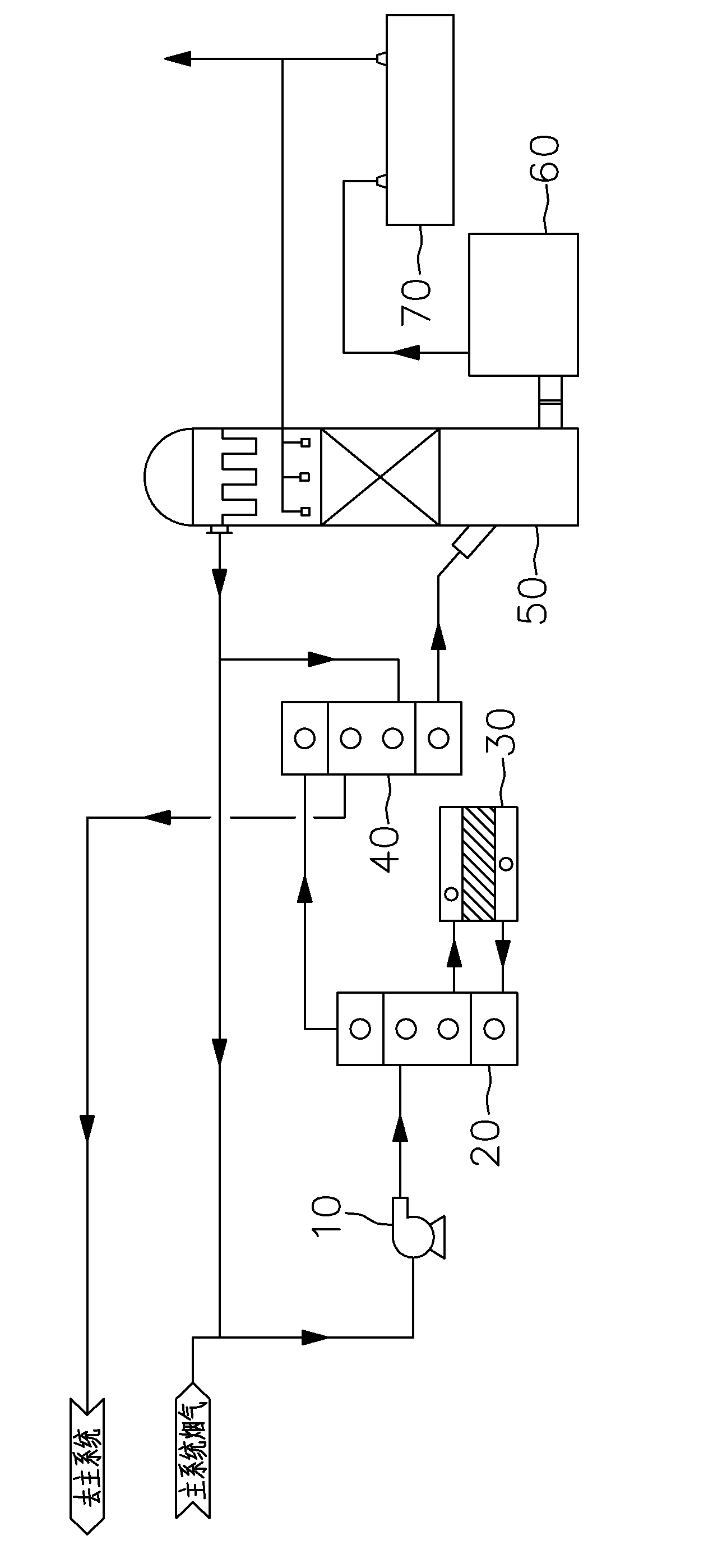
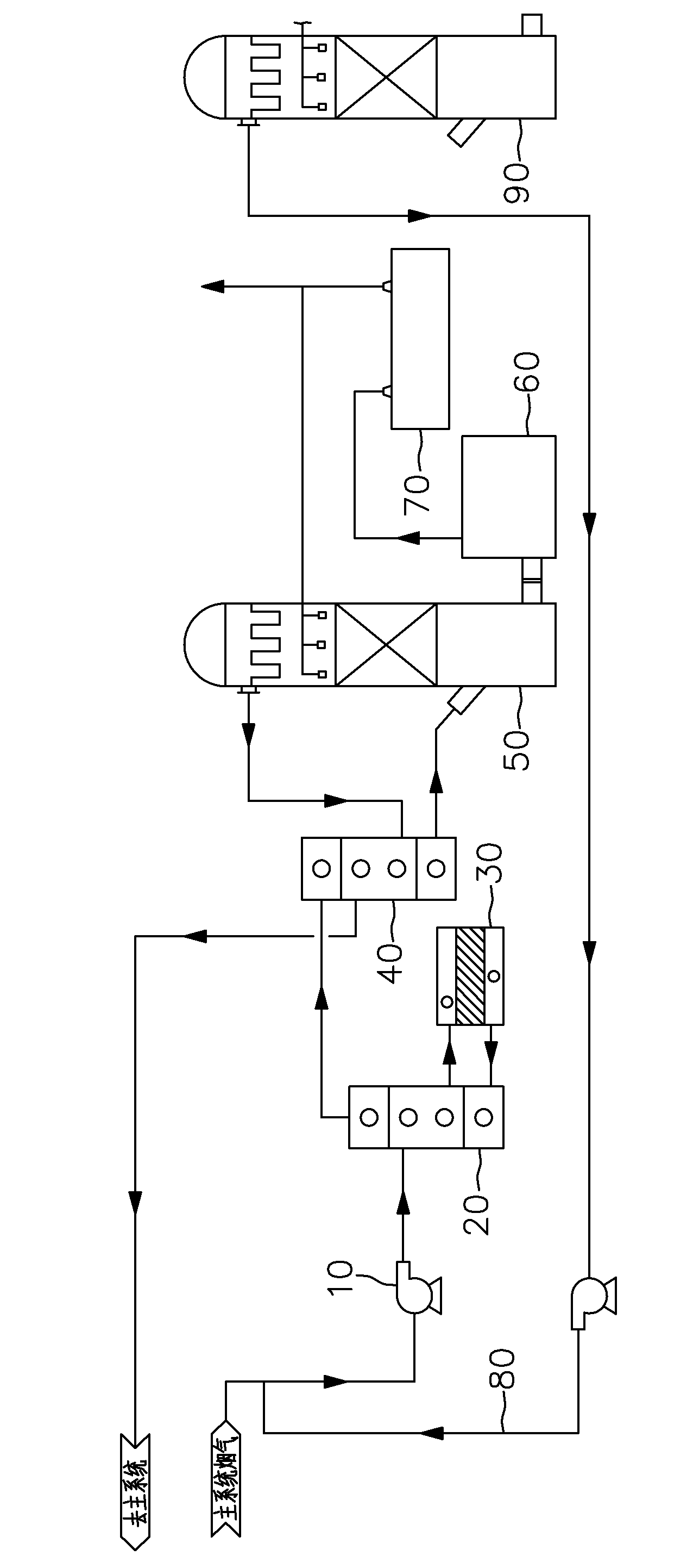
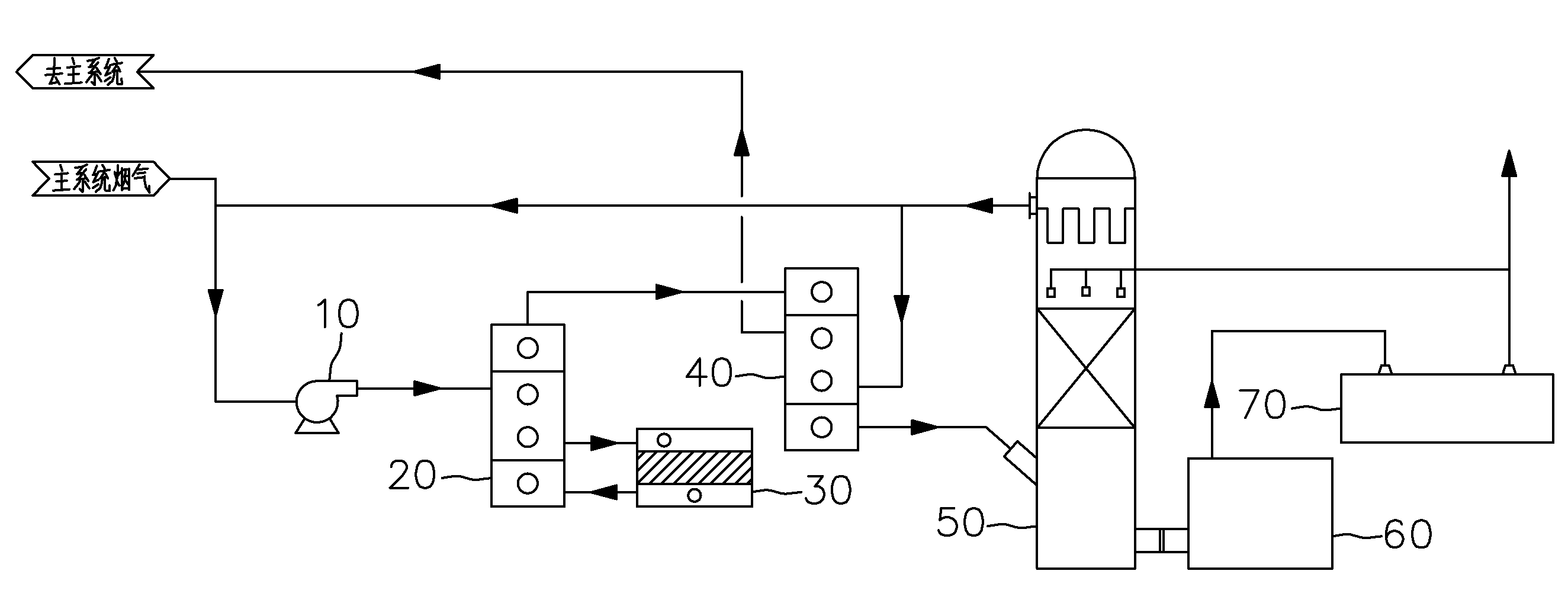
[0022] Such as figure 1 As shown, the SO imported from the main system 2 Flue gas with concentration higher than 13% and SO after pre-reforming and absorbing system treatment 2 Mix flue gas with a concentration lower than 13%, so that the SO of the mixed flue gas 2 If the concentration is lower than 13%, the mixed flue gas is pressurized by the pre-reformer fan 10, heated by the first heat exchanger 20, treated by the pre-reformer 30, heat-exchanged by the first heat exchanger 20 again, and secondly heat-exchanged by the second heat exchanger. heat exchange device 40, and finally enter the pre-absorption tower 50 for treatment to obtain SO 2 The flue gas whose concentration is lower than 13%, the flue gas treated by the pre-absorption tower 50 is divided into two paths, one of which passes through the second exchanger 40 to exchange heat with the SO2 that is ab...


PUM


Abstract

The invention belongs to the technical field of flue gas acid making, in particular to an acid making system suitable for high-concentration sulfur dioxide-containing flue gas. The acid making system comprises a main system used for converting sulfur dioxide-containing flue gas of which the sulfur dioxide concentration is lower than the set sulfur dioxide concentration value for making acid, and a pre-conversion and absorption system used for treating the sulfur dioxide-containing flue gas of which the sulfur dioxide concentration is at least equal to the set sulfur dioxide concentration value into sulfur dioxide-containing flue gas of which the sulfur dioxide concentration is lower than the set sulfur dioxide concentration value, and mixing the treated sulfur dioxide-containing flue gas of which the sulfur dioxide concentration is lower than the set sulfur dioxide concentration value with sulfur dioxide-containing flue gas of which the sulfur dioxide concentration is at least equal to the set sulfur dioxide concentration value and which is about to enter the system, so that the sulfur dioxide concentration value of the flue gas which finally enters the main system is lower than the set value. By the acid making system, diluent air quantity supplemented to the main system is small or even diluent air is not needed to be supplemented; and pre-conversion reaction heat is fully utilized to maintain the heat balance of the whole system, and the load of the main system is not increased through pre-absorption, so that a large amount of equipment investment and operating cost are saved.

Description


Claims


Application Information

Patent Timeline
Owner JINLONG COPPER
Why Eureka
Try Eureka