Low-frequency oscillation real-time control method for power system

A low-frequency oscillation, power system technology, applied in the direction of reducing/preventing power oscillation, can solve the problems of inability to effectively suppress low-frequency oscillation, and inability to achieve real-time control, and achieve the effect of suppressing low-frequency oscillation and ensuring stable operation

Active Publication Date: 2010-08-25
NARI TECH CO LTD +1
View PDF4 Cites 17 Cited by
  • Summary
  • Abstract
  • Description
  • Claims
  • Application Information

AI Technical Summary

Problems solved by technology

Based on the wide area measurement system (WAMS) data platform, the low-frequency oscillation online analysis function can obtain the system's dominant mode and equipment grouping information, identify strongly correlated units and calculate the participation factor, but cannot online analysis and calculation of control measures to suppress oscillation
The small-disturbance stability auxiliary decision-making function is based on the measurement and state estimation results of the Supervisory Control And Data Acquisition (SCADA) system, and can provide control measures to improve the weak damping mode, but is limited by the refresh rate of state estimation and the calculation time of control measures limitations, it is impossible to achieve real-time control
On the other hand, the accuracy of the calculation is limited by the accuracy of the model parameters. Once there is an error in the model parameters, the control measures may not be able to effectively suppress low-frequency oscillations

Method used


Image

  • Low-frequency oscillation real-time control method for power system
  • Low-frequency oscillation real-time control method for power system
  • Low-frequency oscillation real-time control method for power system

Examples


Embodiment Construction

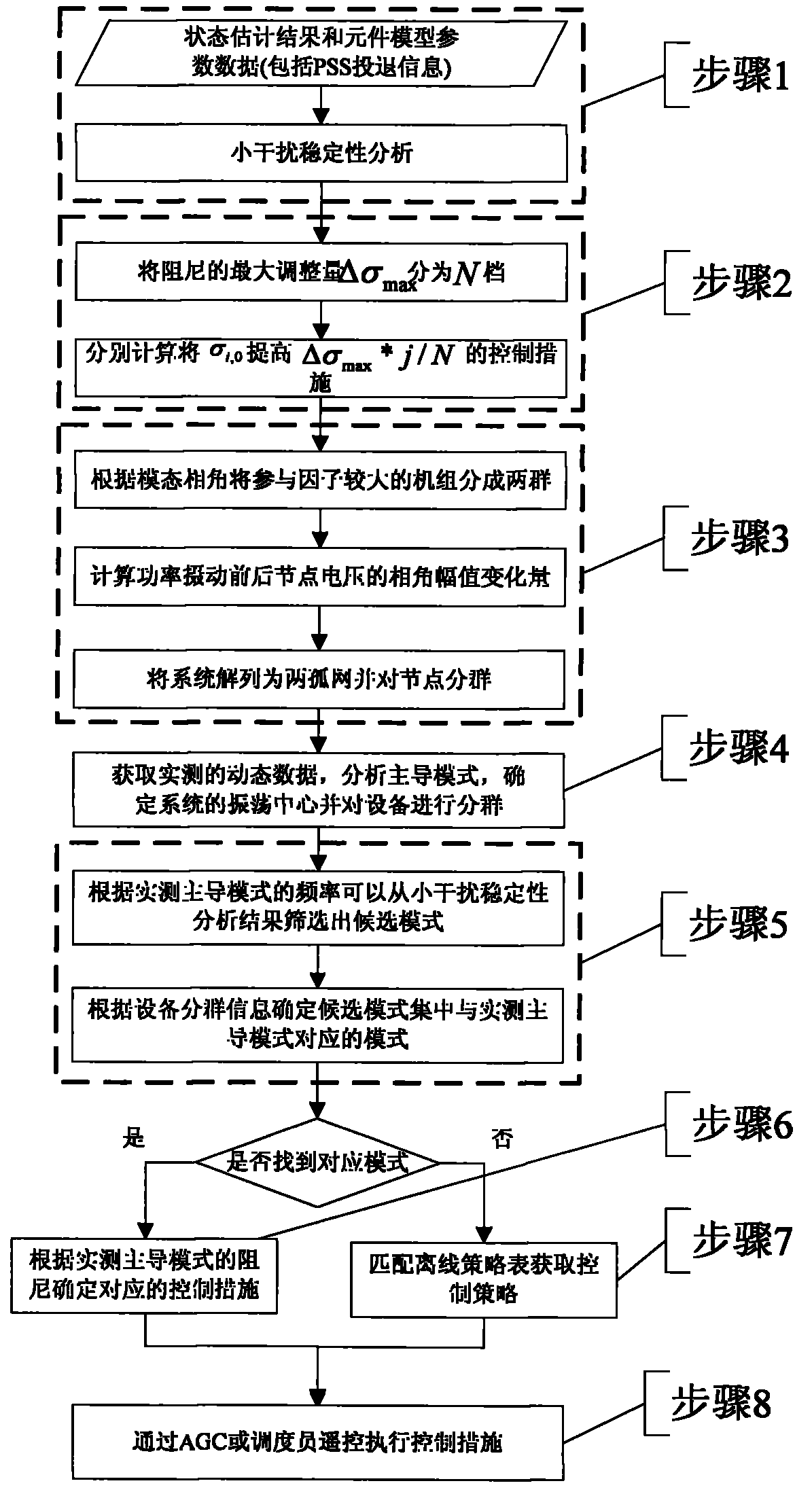
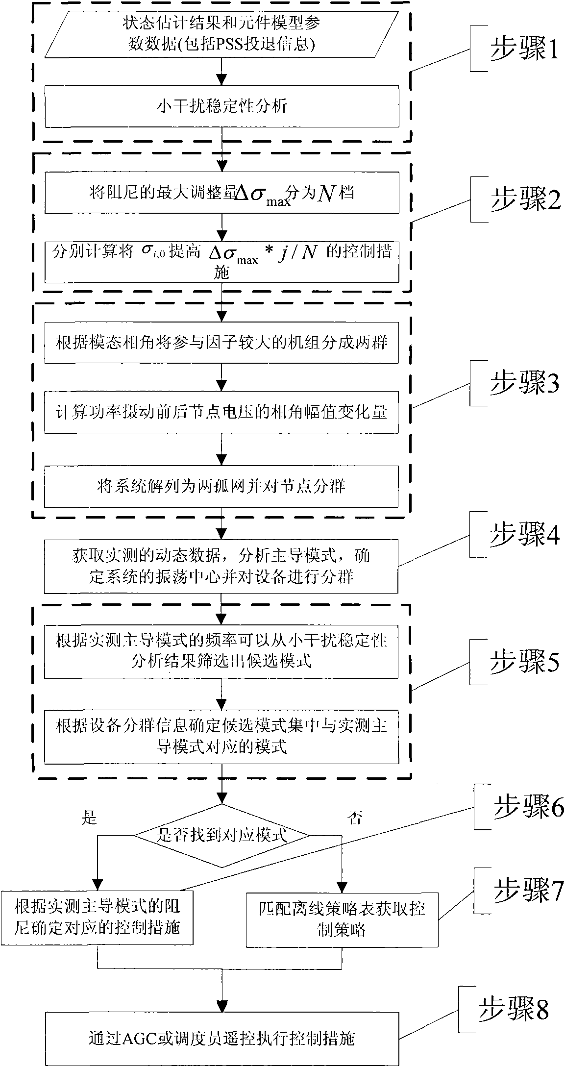
[0017] Below in conjunction with accompanying drawing 1 and accompanying drawing 2, the method of the present invention is described in detail.

[0018] Step 1 in Figure 1 describes the online acquisition of state estimation results, component model parameter data, and PSS commissioning and withdrawal information, and the weak damping mode in the system is calculated by using a given range of eigenvalues.

[0019] Step 2 in Figure 1 describes the control measures to increase the damping of each weak damping mode to different gear values, respectively. The current damping of mode i is σ i,0 , the maximum damping adjustment Δσ of this mode max.i Divided into N i file, respectively calculate the σ i,0 Increase Δσ max.i *j / N i (j=1,...,N i ) control measures, including unit output adjustment and PSS commissioning, etc.

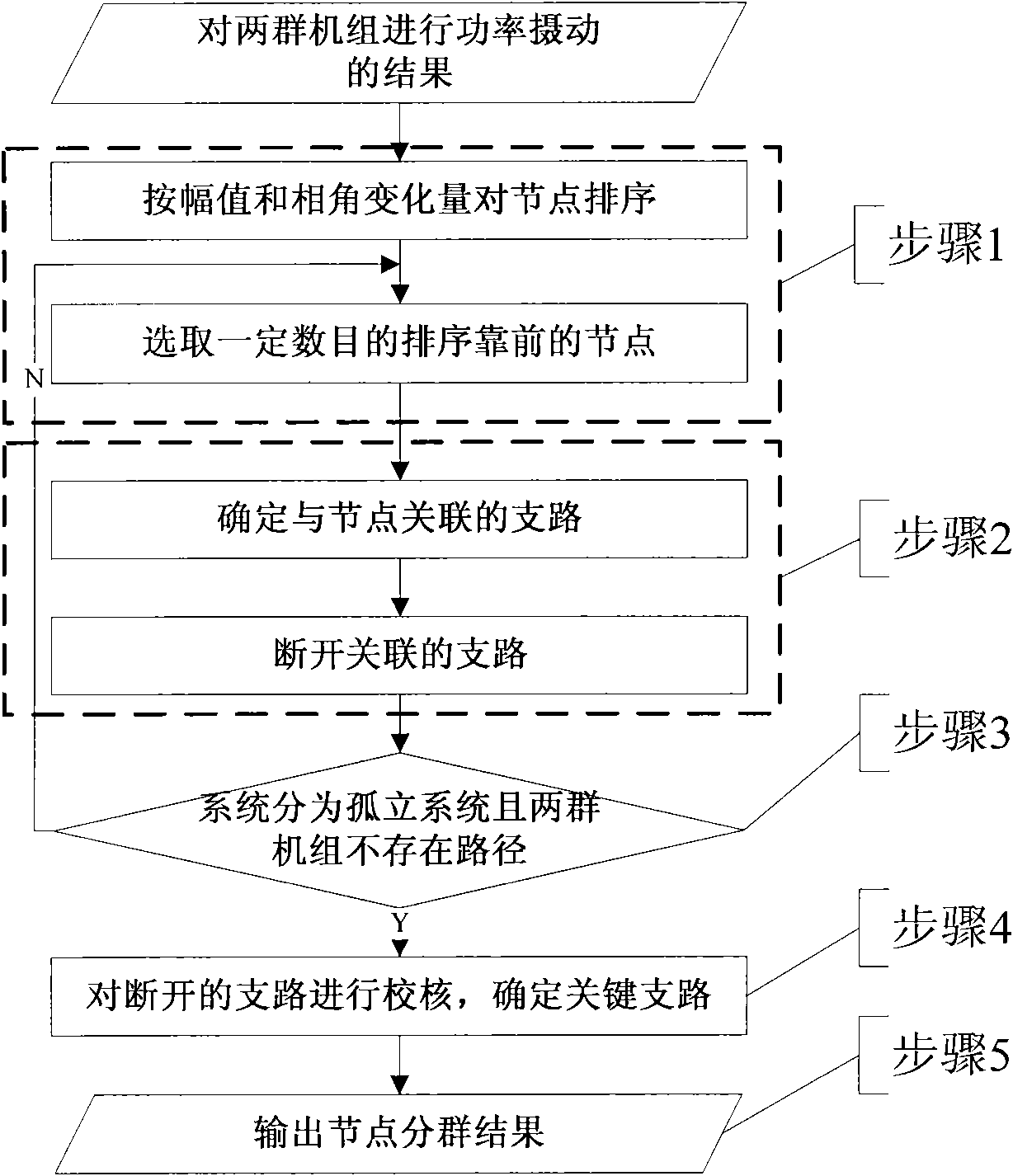
[0020] Step 3 in Figure 1 describes that the units with larger participation factors are divided into two groups according to the modal phase angle; the per...


PUM


Abstract

The method is suitable for applying a small interference stability online control policy or a set offline policy in controlling practical generated low-frequency oscillation. A low-damping mode of a power grid is obtained by small interference stability calculation; control measures for improving the damping of all low-damping modes to different grades are respectively calculated, and oscillationcenters of all the low-damping modes are confirmed according to the physical characteristics of the oscillation centers; and the power grid is divided into two independent networks in the oscillationcenters. When the power grid generates low-frequency oscillation, a candidate mode set is screened by adopting the frequency in an actual measurement leading mode, a mode corresponding to the actual measurement leading mode is confirmed according to actual measured equipment grouping information, and the corresponding control measure is confirmed according to a difference of the actual measurement leading mode damping and a critical safety damping threshold value. If the mode corresponding to the actual measurement leading mode does not exist, the auxiliary decision information is obtained from an offline policy table. Finally, the corresponding control policy is applied by an automatic generation control (AGC) system or an automatic control system of a power plant.

Description

technical field [0001] The invention belongs to the technical field of electric power systems and automation thereof. More precisely, the invention relates to a method for real-time control of low-frequency oscillations in electric power systems. Background technique [0002] Low frequency oscillation is one of the problems that may exist in the regional interconnection grid. Limited by monitoring technology and analysis technology, the current suppression measures for low-frequency oscillation mainly include the installation of power system stabilizers, additional control functions for DC devices and flexible AC devices. Once the operating point of the system exceeds the design range of the controller, low-frequency oscillation may occur. At this time, the dispatcher can only take conservative control measures based on experience, and it may delay the timing of control. Based on the wide area measurement system (WAMS) data platform, the low-frequency oscillation online an...

Claims


Application Information

Patent Timeline
Patent Type & Authority Applications(China)
IPC IPC(8): H02J3/24
Inventor 鲍颜红徐伟徐泰山郑伟刘福锁杨卫东励刚李建华
Owner NARI TECH CO LTD
Why Eureka
Try Eureka