
Switch power supply single-loop constant-frequency hysteresis control method and device thereof

A technology of hysteresis control and switching power supply, which is applied in the direction of control/regulation system, output power conversion device, electrical components, etc. It can solve the problems of converter filter circuit design, EMI suppression difficulty, and affecting switching frequency, etc., and achieves the control method Simple, low-cost, and easy-to-integrate effects

Inactive Publication Date: 2010-08-25
SOUTHWEST JIAOTONG UNIV
View PDF3 Cites 2 Cited by
  • Summary
  • Abstract
  • Description
  • Claims
  • Application Information

AI Technical Summary

Problems solved by technology

However, hysteresis control is a variable frequency control method, and the working state of the converter will affect the switching frequency, which will bring difficulties in the design of the converter filter circuit, EMI suppression, etc.

Method used


Image

  • Switch power supply single-loop constant-frequency hysteresis control method and device thereof
  • Switch power supply single-loop constant-frequency hysteresis control method and device thereof
  • Switch power supply single-loop constant-frequency hysteresis control method and device thereof

Examples


Embodiment 1

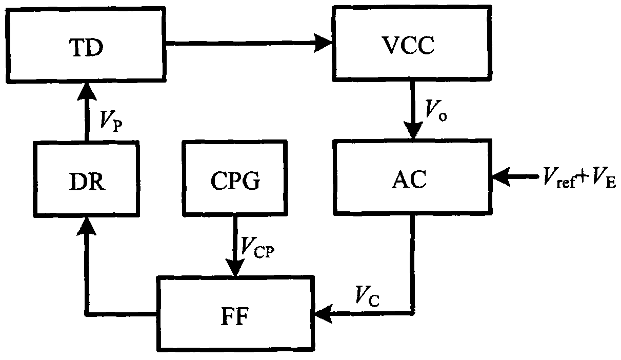
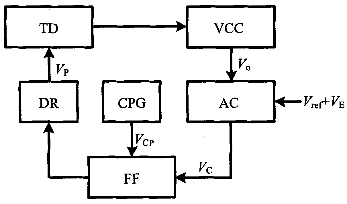
[0035] Fig. 1 shows, a kind of embodiment of the present invention is, the single-loop fixed-frequency hysteresis control method of switching power supply, and its specific practice is:

[0036] At the beginning of each switching cycle, the clock signal generator CPG sends out a clock pulse V CP, the flip-flop FF is set to output a high level, and the switch tube S in the converter TD is controlled by the drive circuit DR to conduct, and the converter output voltage V o rising; the voltage detection circuit VCC detects the output voltage V o , and place V o The voltage signal is output to the comparator AC; the comparator AC converts V o Same as preset voltage value V ref +VE is compared and output to flip-flop FF, when V o less than V ref +V E , the flip-flop FF remains in the same state when V o rise to V ref +V E When , the output signal of the comparator AC jumps, and makes the flip-flop FF reset and output a low level, the switch tube S is turned off, and the con...

Embodiment 2

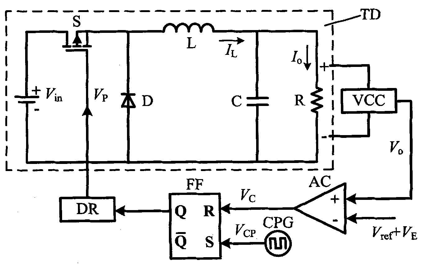
[0048] Fig. 6 shows that this example is basically the same as the first example, except that the second example adopts the second specific method of the control method of the present invention, and the controller controls the valley value of the output voltage ripple of the converter. Therefore, compared with Embodiment 1, the controller structure in Embodiment 2 has the following differences: the output terminal of the voltage detection circuit VCC is connected to the negative polarity terminal of the comparator AC; the output terminal of the comparator AC is connected to the S of the flip-flop FF The terminal is connected; the output terminal of the clock signal generator CPG is connected with the R terminal of the flip-flop FF.

[0049] The converter TD of the switching power supply controlled in this example is a Boost converter, as shown in Figure 6.

Embodiment 3

[0051] Fig. 7 shows that this example is basically the same as the first example, except that the converter TD of the switching power supply controlled by this example is a single-ended forward converter.

[0052] The method of the invention is a fixed-frequency control method, and the switching frequency of the switching power supply is determined by an external clock pulse. Its control device can be realized with analog devices or digital devices conveniently; in addition to being used in the switching power supply composed of the converters in the above embodiments, it can also be used in Buck-Boost converters, Cuk converters, BIFRED converters, and flyback converters. Converter, half-bridge converter, full-bridge converter and other power circuits form a switching power supply.

[0053] In addition, it should be mentioned again that the two specific control methods of the present invention and the corresponding specific control devices have isomorphism, and are two specifi...


PUM


Abstract

The invention discloses a switch power supply single-loop constant-frequency hysteresis control method and device thereof. Control is realized by controlling peak value or valley value of converter output voltage ripple in each switching period. When adopting peak value control, at the initial t0 moment of one switching period, a switching tube is on, and switching converter output voltage Vo rises; when Vo rises to the standard voltage Vref, the switching tube is still in on state; when Vo rises to Vref+VE, the switching tube is cut off, and Vo is dropped correspondingly; then at the t0+T moment, the switching tube is turned on again, and the converter operates in the next switching period. The converter adopting the method of the invention has fixed switching frequency, good transient performance and simple control circuit, only detection on converter output voltage is required and no compensation link is required, and the invention is applicable to converters in various topology structures.

Description

technical field [0001] The invention relates to a control method and a device for a switching power supply. Background technique [0002] In recent years, with the rapid development of electronic technology and information technology, switching power supply has become a hot spot in engineering application and academic research in the field of power electronics technology. Microprocessors, communication equipment, industrial control equipment, medical equipment, electric vehicles, etc. Performance DC switching power supply as its power supply equipment. [0003] A switching power supply system generally consists of a power main circuit and a control circuit. The power main circuit (that is, the switching converter) mainly includes switching tubes, rectification and filtering circuits, isolation transformers, etc.; the topology types of switching converters include Buck, Boost, Flyback, Full-Bridge, etc. The control circuit (that is, the controller) is used to detect the wor...

Claims


Application Information

Patent Timeline
Patent Type & Authority Applications(China)
IPC IPC(8): H02M3/155H02M3/335
Inventor 秦明许建平王金平张斐周国华
Owner SOUTHWEST JIAOTONG UNIV
Features
  • Generate Ideas
  • Intellectual Property
  • Life Sciences
  • Materials
  • Tech Scout
  • Unparalleled Data Quality
  • Higher Quality Content
  • 60% Fewer Hallucinations
Learn More