Step-down constant current LED drive circuit for automobile lighting

A technology for LED driving and automotive lighting, which is applied in the field of electric lighting, and can solve problems that affect the service life of high-power LEDs, short circuits, open circuits, and LED driver module failures.

Inactive Publication Date: 2012-11-28
HASCO VISION TECHNOLOGY CO LTD
View PDF0 Cites 0 Cited by
  • Summary
  • Abstract
  • Description
  • Claims
  • Application Information

AI Technical Summary

Problems solved by technology

However, for the circuit topology of the step-down circuit, some PWM modulation chips without MOS tube driving capability cannot drive the MOS tube. To achieve a complete turn-on and cut-off state, the abnormal state of the MOS tube will affect the normal operation of the entire LED drive circuit
A common method of driving the gate is a gate driver, but the price of a dedicated gate driver chip is relatively high
[0006] On the other hand, LED driver modules are used in the field of automotive lights, and short circuits and open circuits often occur in the production line or installation wiring process, resulting in the failure and damage of the entire LED driver module
[0007] For the thermal problems of high-power LEDs, since the current value of LEDs will change with temperature, when the current is too high, the temperature will also increase, which will affect the service life of high-power LEDs

Method used


Image

  • Step-down constant current LED drive circuit for automobile lighting
  • Step-down constant current LED drive circuit for automobile lighting

Examples


Embodiment

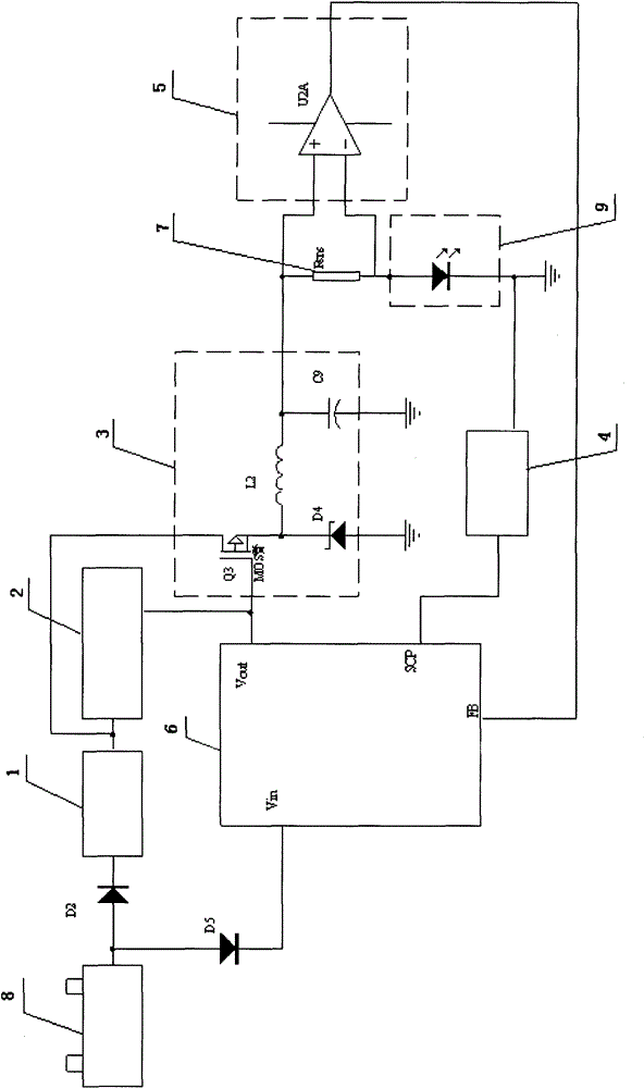
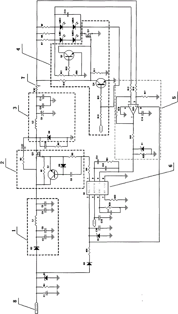
[0022] as attached figure 1 As shown, a step-down constant current LED drive circuit for automotive lighting includes: isolation circuit module 1, MOS tube drive circuit module 2, conversion circuit module 3, PWM control chip 6 (the chip model adopted is Texas Instruments TI The company's TL5001 series chip), feedback circuit module 5 and protection circuit module 4; the DC power supply 12V for automobiles supplies power to the isolation circuit module 1 through the anti-reverse diode D2, and the signal filtered by the isolation circuit module 1 is output to the MOS tube drive The circuit provides the MOS transistor Q3 with a gate-source voltage difference sufficient to turn it on and off, and at the same time, the PWM control chip 6 outputs a square wave pulse signal to the MOS transistor Q3 to control the opening and closing of the MOS transistor Q3, and the on-off duty ratio of the MOS transistor Q3 goes to To control the energy of the conversion circuit, the conversion cir...


PUM


Abstract

The invention relates to a step-down constant current LED drive circuit for automobile lighting. The circuit comprises an isolating circuit module (1), wherein the input end of the isolating circuit module (1) is electrically connected with a power supply (8), and the output end of the isolating circuit module (1) is electrically connected with an MOS transistor drive circuit module (2) and a converting circuit module (3); a Vin terminal of a PWM control chip (6) is electrically connected with the power supply (8), and a Vout terminal of the PWM control chip (6) is electrically connected withthe MOS transistor drive circuit module (2) and the converting circuit module (3); the output end of the converting circuit module (3) is connected with an LED lamp set (9); one end of a feedback circuit module (5) is connected with the output of the converting circuit module (3) and the LED lamp set (9), and the other end of the feedback circuit module (5) is connected with an FB terminal of thePWM control chip; and a protection circuit module (4) is arranged between an earth terminal of the LED lamp set (9) and an SCP terminal of the PWM control chip. The drive circuit of the invention notonly make the LED emit light constantly, but also has a short-circuit protection function, high rate of qualified products and low cost.

Description

technical field [0001] The invention belongs to the field of electric lighting, in particular to an LED driving circuit, in particular to a step-down constant current LED driving circuit for automobile lighting. Background technique [0002] In the mid-1980s, LEDs (Light Emitting Diodes, light-emitting diodes) began to be used in automobile central high mount stop lamps (CHMSL, Central High Mounted Stop Lamp). Panel backlighting generally adopts LED as a new solid-state light source. After entering the new century, with the improvement of LED power and brightness, in addition to automobile headlights, LED has fully entered the application of automobile lighting and signal systems. [0003] LED has significant advantages such as fast response speed, low power consumption, energy saving, and long life. Due to the fast response speed of LED, it is especially suitable for the application of automobile brake lights and turn signals, which can reduce the probability of traffic ac...

Claims


Application Information

Patent Timeline
Patent Type & Authority Patents(China)
IPC IPC(8): H05B37/02
Inventor 李佳颖夏盛
Owner HASCO VISION TECHNOLOGY CO LTD
Why Eureka
Try Eureka