Artificial lift mechanisms

A kind of artificial and component technology, applied in the direction of mechanical equipment, machine/engine, liquid variable displacement machinery, etc., can solve the problem of gas spring counterweight without storage and recirculation, etc., to eliminate the risk of fire or explosion, simplify stockholding, The effect of service time minimization

Inactive Publication Date: 2010-08-25
CROSTEK MANAGEMENT CORP
View PDF7 Cites 2 Cited by
  • Summary
  • Abstract
  • Description
  • Claims
  • Application Information

AI Technical Summary

Problems solved by technology

[0023] 1. None of the proposed types of linear motors can generate the required mechanical force while being of reasonable size, weight, efficiency and cost;
[0024] 2. None of the proposed counterweight systems constantly adapt to changes in pumping conditions in order to minimize the dynamic load on the linear motor;
[0025] 3. None of the proposed gas spring weights are continuously optimized for energy storage and recirculation in the reciprocating mechanism; and
[0026] 4. None of the proposed types of linear motors are inherently load-sensing such that their current command signal can be used to control the mechanism as a whole

Method used


Image

  • Artificial lift mechanisms
  • Artificial lift mechanisms
  • Artificial lift mechanisms

Examples


Embodiment Construction

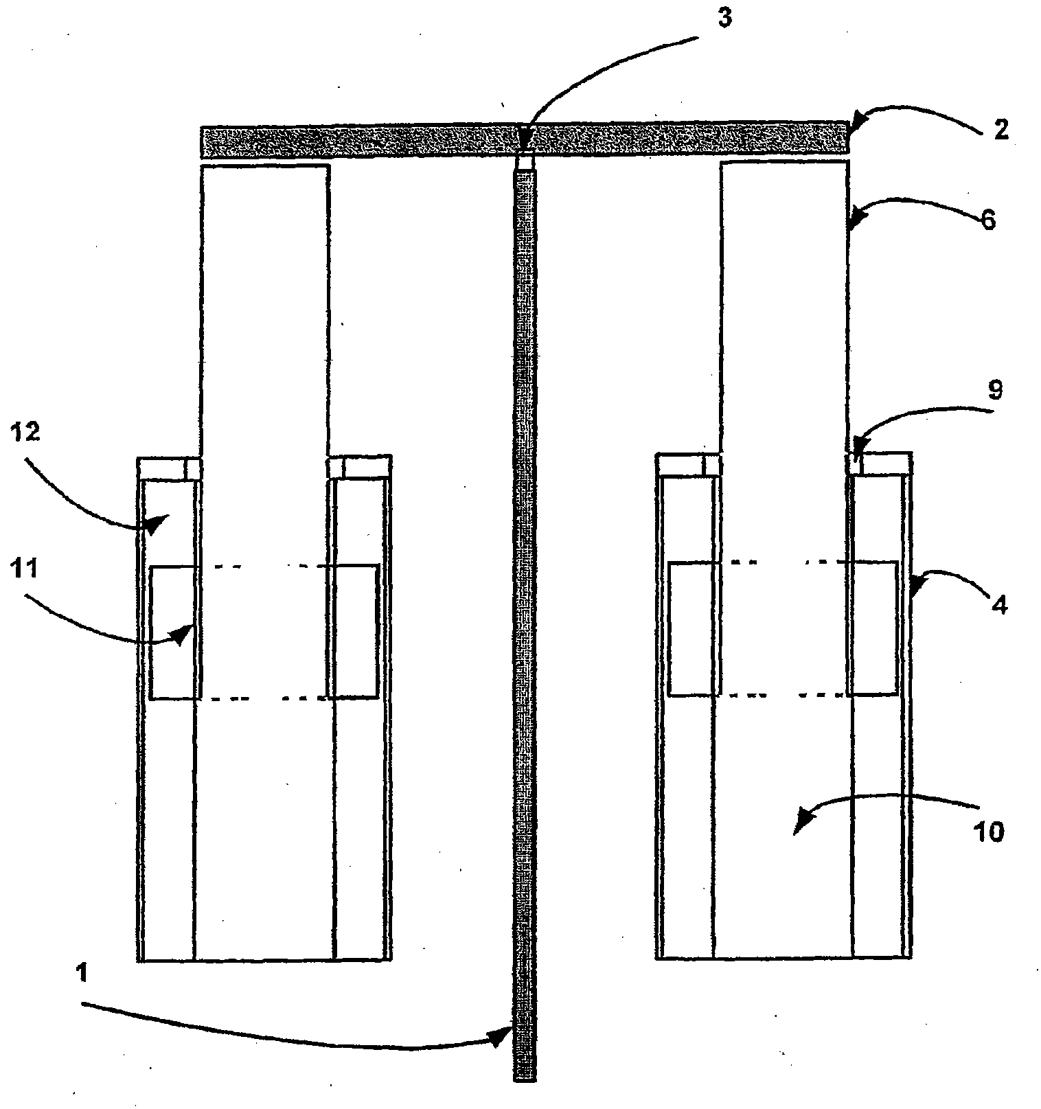
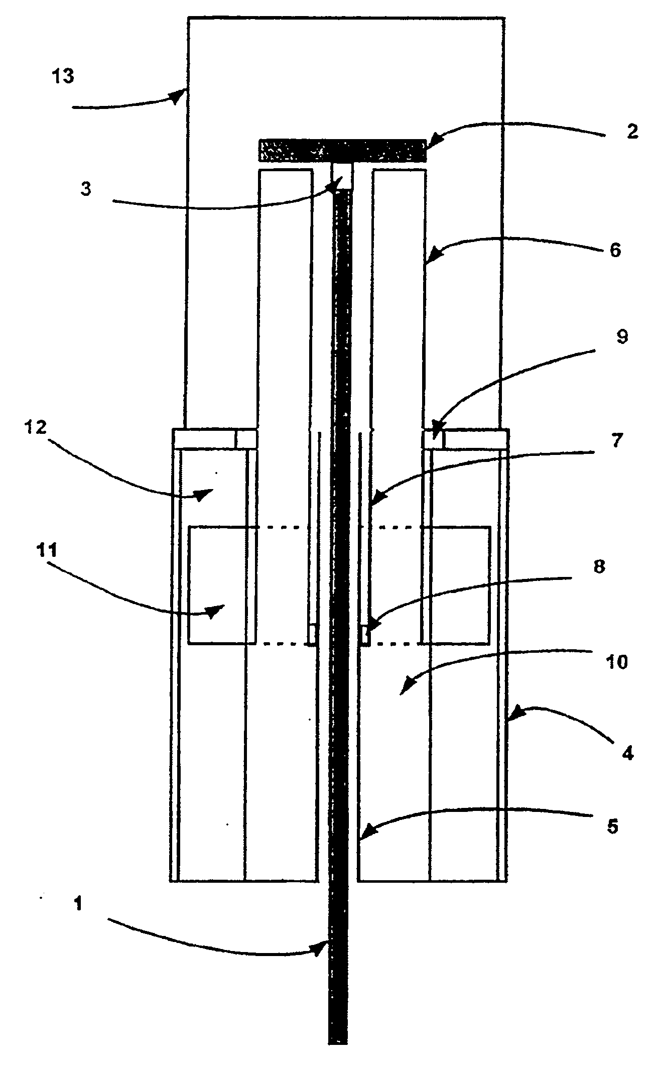
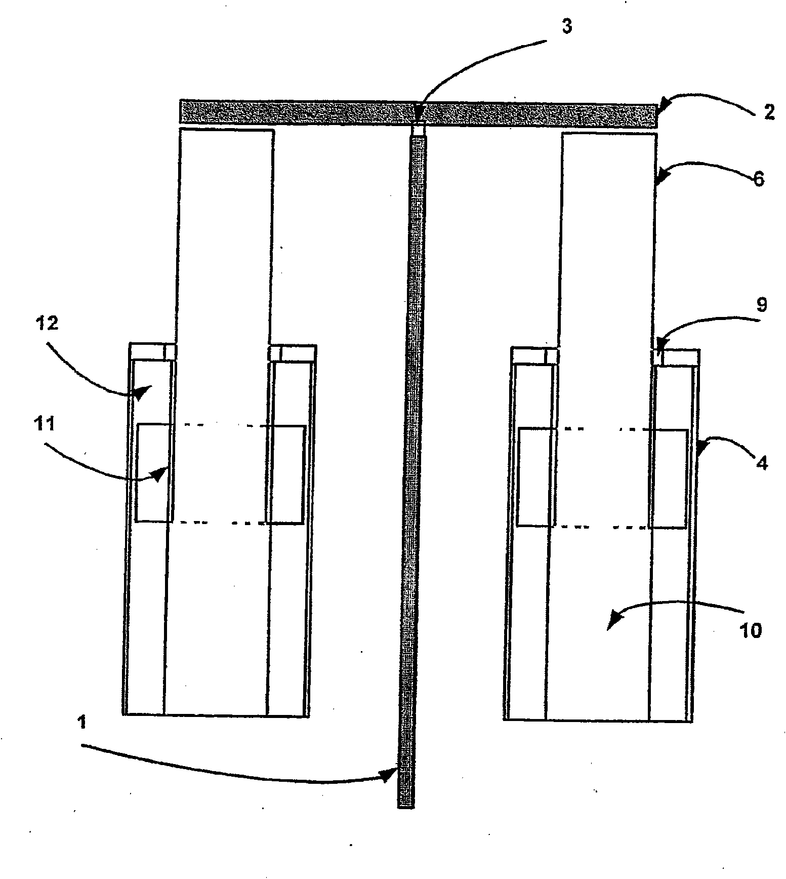
[0058] Referring to Figure 1 , there is shown a longitudinal section view of the basic cylindrical mechanism in which the polished rod 1 of the pumping string is suspended from the disc 2 by a shackle or flexible coupling 3 . Flexible couplings are necessary to accommodate slight tolerances that may exist in alignment or may occur momentarily between the axis of the machine and the direction of the applied force. The rod 1 passes through a cylindrical passage or cavity in the body of the mechanism delimited by the upper tube 7 and the lower tube 5 . The interior of the mechanism is made airtight by a sealed bearing unit 8 located between the coaxial tubes 5 and 7 .

[0059] The mast 1 is raised and lowered by means of an extendable cylinder 6 with a disc 2 attached to the top outer surface of the cylinder. The cylinder 6 extends iteratively from the base body of the machine 4 through the second bearing sealing unit 9 . The position of the cylinder 6 is controlled by the forc...


PUM


Abstract

The invention relates to electric linear motors and gas springs in reciprocating pumps for oil wells. By the use of this invention a simple, silent, compact and adaptable mechanism can be constructed to drive a wide range of such pumps. The mechanism will sense a variety of pumping conditions and react automatically thereto.

Description

technical field [0001] This invention relates to a form of mechanism intended to drive a reciprocating pump to lift liquid from a deep well or mine. Background technique [0002] In an "oil field pump" mechanism, the piston and non-return valve unit at the bottom of a well or mine (possibly thousands of meters deep) are collectively connected to the drive mechanism at the surface by long steel rods assembled in segments and screwed together. Connected together, called pole column (rod string). The segment at the top of the rod—the segment that emerges from the wellbore through the pressure seal—necessarily has a high surface finish, called polished rod. The polishing rod is directly connected to the reciprocating mechanism that makes up the invention described herein. [0003] It has long been known to construct such a mechanism in the form of an oscillating horizontal beam with a hammer-shaped end in which is wound a chain or cable from which the pumping string is suspend...

Claims


Application Information

Patent Timeline
Patent Type & Authority Applications(China)
IPC IPC(8): F04B47/04E21B43/12F04B17/04F04B47/02
CPCE21B43/127F04B47/04F04B17/042F04B47/02E21B43/13E21B43/126
Inventor 菲利普·德纳
Owner CROSTEK MANAGEMENT CORP
Why Eureka
Try Eureka