Self-piercing frictional rivet welding connecting device

A riveted welding connection and self-piercing technology, applied in welding equipment, non-electric welding equipment, manufacturing tools, etc., can solve the problems of difficult deformation of high-strength steel self-piercing riveting, low friction spot welding efficiency, and reduced feed resistance. Riveting force and requirements for equipment rigidity, the effect of improving connection efficiency and joint strength

Inactive Publication Date: 2010-09-01
SHANGHAI JIAO TONG UNIV +1
View PDF5 Cites 71 Cited by
  • Summary
  • Abstract
  • Description
  • Claims
  • Application Information

AI Technical Summary

Problems solved by technology

[0005] The purpose of the present invention is to overcome the deficiencies of the prior art and provide a self-piercing friction riveting welding connection device, which is based on the mechanical connection of the self-piercing riveting process and introduces the solid-phase connection mechanism of the friction stir spot welding process, through which the rivet rotates at a high speed Generating frictional heat to sof

Method used


Image

  • Self-piercing frictional rivet welding connecting device
  • Self-piercing frictional rivet welding connecting device
  • Self-piercing frictional rivet welding connecting device

Examples


Embodiment 1

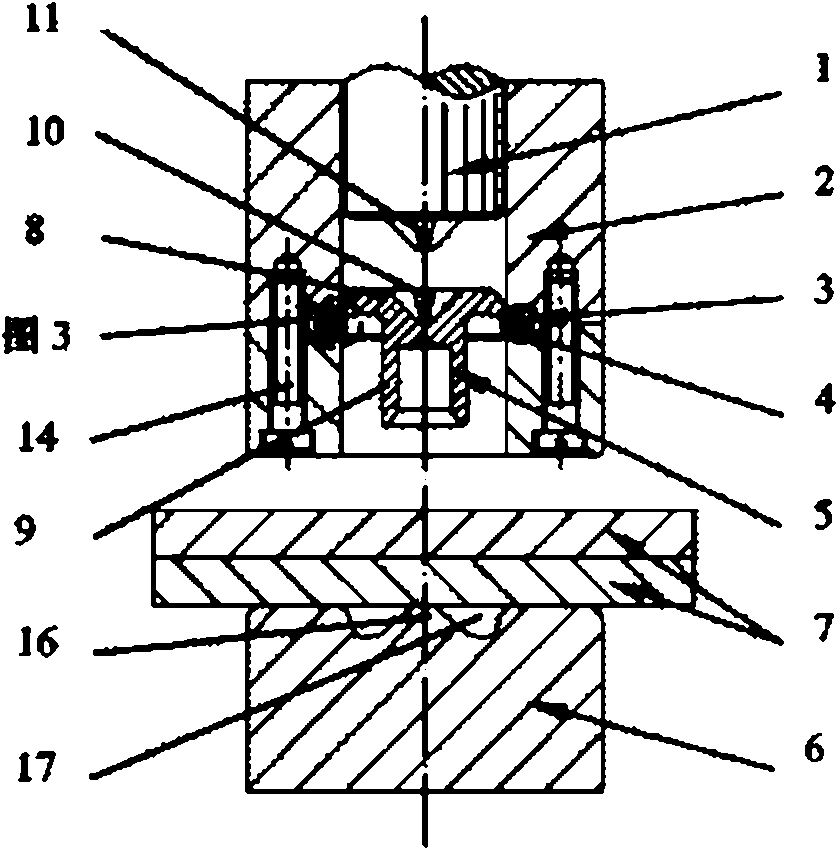
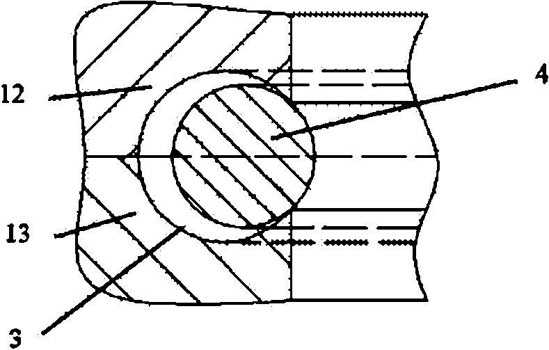
[0023] like figure 1 As shown, this embodiment includes: a driving pin 1, a blank holder 2, an annular guide groove 3, an annular positioning spring 4, a semi-tubular rivet 5, a die 6 and a plate 7, wherein: the blank holder 2 is sleeved to drive Needle 1, a semi-hollow rivet 5 is provided under the driving pin 1, an annular guide groove 3 is provided on the inner wall of the blank holder 2, an annular positioning spring 4 is arranged in the annular guide groove 3, and the semi-hollow rivet 5 is positioned on the annular positioning spring 4 Above, the die 6 is set under the semi-tubular rivet 5 , and the plate 7 is set on the die 6 .

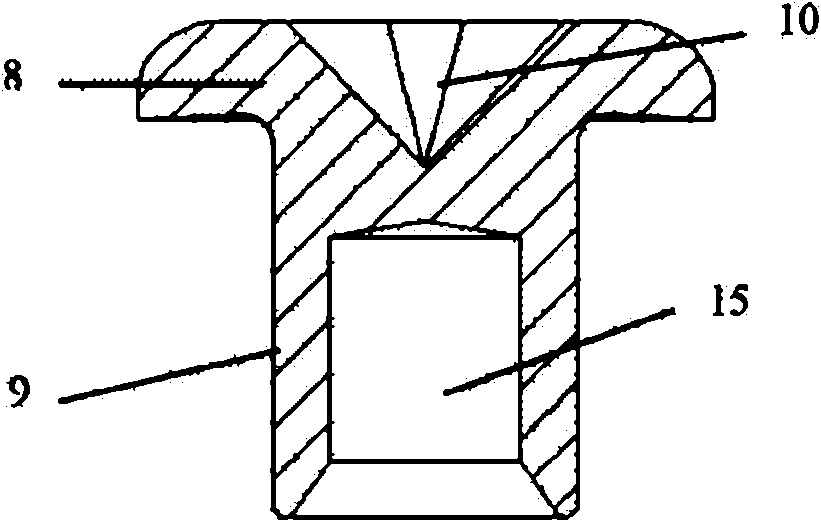
[0024] like figure 2 As shown, the semi-tubular rivet 5 includes: a rivet head 8 and a rivet leg 9, wherein: the center of the rivet head 8 is provided with a groove 10, the rivet head 8 is fixedly provided with a rivet leg 9, and the diameter of the rivet head 8 is larger than that of the rivet leg 9 path.

[0025] The shape of the rivet h...

Embodiment 2

[0043] The plate 7 in this implementation is: strong steel DP780 + aluminum alloy AA6061-T6, that is, the high-strength steel is on the top and the aluminum alloy is on the bottom; the thickness of the plate is matched: 1.4mm+2mm;

[0044] Process parameters: the rotation speed of the driving pin 1 and the rivet meshing stage is 90r / min, the feeding speed of the driving pin 1 is 30mm / s; Hold for 40ms after the stroke ends.

[0045] Other implementation modes of this embodiment are the same as Embodiment 1.


PUM

PropertyMeasurementUnit
Angleaaaaaaaaaa
Depthaaaaaaaaaa
Lengthaaaaaaaaaa

Abstract

The invention relates to a self-piercing frictional rivet welding connecting device which belongs to the technical field of rivet welding. The device comprises a driving needle, a blank holder, an annular guide slot, an annular positioning spring, a semi-tubular rivet and a female die, wherein the driving needle is sleeved in the blank holder; the semi-tubular rivet is positioned below the driving needle; the annular guide slot is formed in the blank holder; the annular positioning spring is arranged in the annular guide slot; the semi-tubular rivet is positioned on the annular positioning spring; and the female die is arranged below the semi-tubular rivet. The high-strength steels are softened by using the friction heat generated by speedily rotating the rivet so the percentage of elongation of the high-strength steel is increased, the riveting force and the rigid requirement on equipment are reduced, the joint efficiency of friction stir spot welding is improved, the technical shrinkage pool is eliminated, the joint strength is efficiently increased, the mechanical-solid phase double joint is realized and the static and dynamic mechanical properties of the joint are greatly improved. The connecting device of the invention is applied to the connection between the light alloy and the high-strength steel and is also applied to the connection between the different light alloys and between different high-strength steels.

Description

technical field [0001] The invention relates to a device in the technical field of rivet welding, in particular to a self-piercing friction rivet welding connection device. Background technique [0002] Resistance spot welding is the most important connection method in car body assembly. Due to the huge difference in thermophysical properties between light alloys and high-strength steels and the formation of hard and brittle intermetallic compounds during welding, it is difficult to achieve using traditional resistance spot welding processes. Connection; while the traditional riveting method requires pre-punching holes before fastening the rivets, resulting in complex process and low production efficiency, so it is not suitable for mass assembly of body panels. [0003] In view of the above-mentioned problems in the point connection between light alloy and high-strength steel, rivetless riveting (Clinching), semi-hollow rivet self-piercing riveting (Self-Piercing Riveting, r...

Claims


Application Information

Patent Timeline
IPC IPC(8): B23P23/04B21J15/10B23K20/12
CPCB21J15/027B21J15/025
Inventor 林忠钦李永兵王培中来新民楼铭陈关龙
Owner SHANGHAI JIAO TONG UNIV
Why Eureka
Try Eureka