Jet-printing head based on double-carbon nanotube microbubble generator and preparation method thereof
A micro-bubble generator, carbon nanotube technology, applied in printing and other directions, can solve problems such as high power consumption, and achieve the effects of low power consumption, improved quality, and high integration density
- Summary
- Abstract
- Description
- Claims
- Application Information
AI Technical Summary
Problems solved by technology
Method used
Image
Examples
Embodiment 1
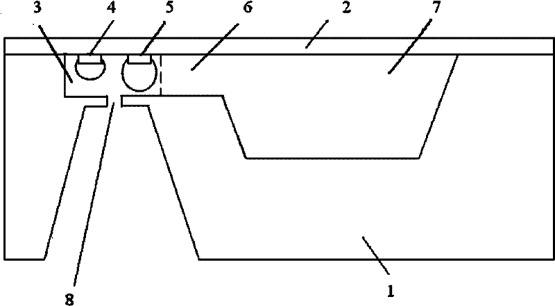
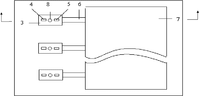
[0081] (1) Adopt glass as the cover plate 2, and carry out surface treatment and cleaning to the glass cover plate;
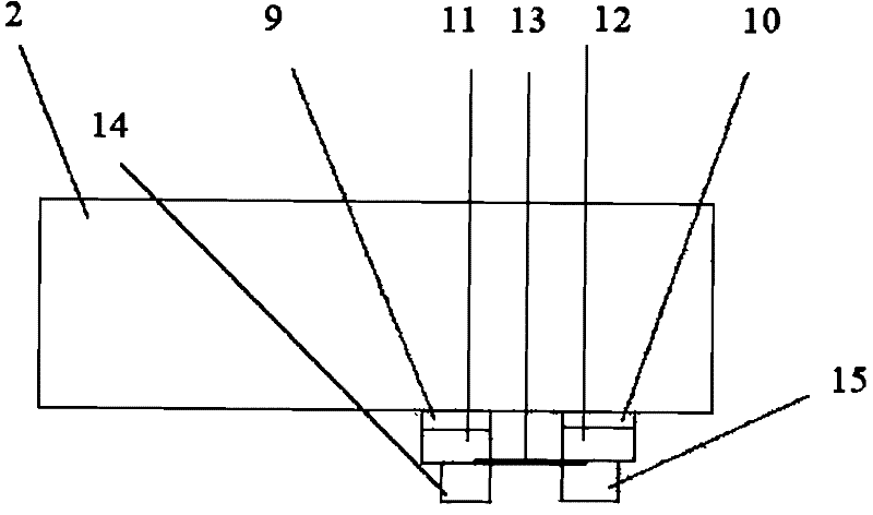
[0082] (2) The carbon nanotube microbubble generator is prepared on the cover plate 2, and the process is as follows:
[0083] (2.1) Evaporating titanium with an electron beam to form a titanium film with a thickness of 20nm;
[0084] (2.2) Evaporating gold by electron beam to form a gold film with a thickness of 400nm;
[0085] (2.3) Forming gold electrodes 11, 12 using the existing lift-off process (lift-off), the distance between the gold electrodes 11, 12 is 5 μm;
[0086] (2.4) Mix carbon nanotubes 13 with a diameter of 10 to 30 nm and anhydrous ethanol solvent at a ratio of 0.01 mg / ml, and disperse the carbon nanotubes uniformly by ultrasonication;
[0087] (2.5) Apply an AC voltage of 1MHz and 8V between the gold electrodes 11 and 22 on the cover plate 2, drop the suspension of carbon nanotubes between the electrodes with a micro-syringe, and when the ...
Embodiment 2
[0132] (1) Glass is used as the cover plate 2, and the cover plate 2 is subjected to surface treatment and cleaning;
[0133] (2) The carbon nanotube microbubble generator is prepared on the cover plate 2, and the process is as follows:
[0134] (2.1) Adopt sputtering titanium to form a titanium film with a thickness of 30nm;
[0135] (2.2) Adopt sputtering gold to form a gold film with a thickness of 300nm;
[0136] (2.3) Forming gold electrodes 11, 12 using the existing lift-off process (lift-off), the distance between the gold electrodes 11, 12 is 1 μm;
[0137] (2.4) Mix carbon nanotubes 13 with a diameter of 10 to 30 nm and absolute ethanol solvent at a ratio of 0.005 mg / ml, and disperse the carbon nanotubes uniformly by ultrasound;
[0138] (2.5) 0.5MHz, 5V AC voltage is loaded between the gold electrodes 11 and 12 on the cover plate 2, and the carbon nanotube suspension is dropped between the electrodes with a micro-syringe. When the solvent evaporates completely, the...
Embodiment 3
[0157] (1) Glass is used as the cover plate 2, and the cover plate 2 is subjected to surface treatment and cleaning;
[0158] (2) The carbon nanotube microbubble generator is prepared on the cover plate 2, and the process is as follows:
[0159] (2.1) Adopt sputtering titanium to form a titanium film with a thickness of 30nm;
[0160] (2.2) Adopt sputtering gold to form a gold film with a thickness of 300nm;
[0161] (2.3) Forming gold electrodes 11, 12 using the existing lift-off process (lift-off), the distance between the gold electrodes 11, 12 is 10 μm;
[0162] (2.4) Mix carbon nanotubes 13 with a diameter of 10 to 30 nm and absolute ethanol solvent at a ratio of 0.05 mg / ml, and disperse the carbon nanotubes uniformly through ultrasound;
[0163] (2.5) 0.8MHz, 10V AC voltage is loaded between the gold electrodes 31 and 32 on the glass substrate 1, and the carbon nanotube suspension is dropped between the electrodes with a micro-injector. When the solvent evaporates comp...
PUM
| Property | Measurement | Unit |
|---|---|---|
| thickness | aaaaa | aaaaa |
| thickness | aaaaa | aaaaa |
| diameter | aaaaa | aaaaa |
Abstract
Description
Claims
Application Information
 - R&D
- Intellectual Property
- Life Sciences
- Materials
- Tech Scout
- Unparalleled Data Quality
- Higher Quality Content
- 60% Fewer Hallucinations
Browse by: Latest US Patents, China's latest patents, Technical Efficacy Thesaurus, Application Domain, Technology Topic, Popular Technical Reports.
© 2025 PatSnap. All rights reserved.Legal|Privacy policy|Modern Slavery Act Transparency Statement|Sitemap|About US| Contact US: help@patsnap.com


