Thermal control of the bead portion of a glass ribbon

A technology of glass ribbon and curling, which is applied in glass forming, glass forming, glass manufacturing equipment, etc., and can solve problems such as defective displays

Inactive Publication Date: 2010-09-01
CORNING INC
View PDF5 Cites 16 Cited by
  • Summary
  • Abstract
  • Description
  • Claims
  • Application Information

AI Technical Summary

Problems solved by technology

Although the amount of shape change described above is usually small from the perspective of the pixel structures used in modern displays, the distortions due to cutting can be large enough to result in a considerable number

Method used


Image

  • Thermal control of the bead portion of a glass ribbon
  • Thermal control of the bead portion of a glass ribbon
  • Thermal control of the bead portion of a glass ribbon

Examples


example 1

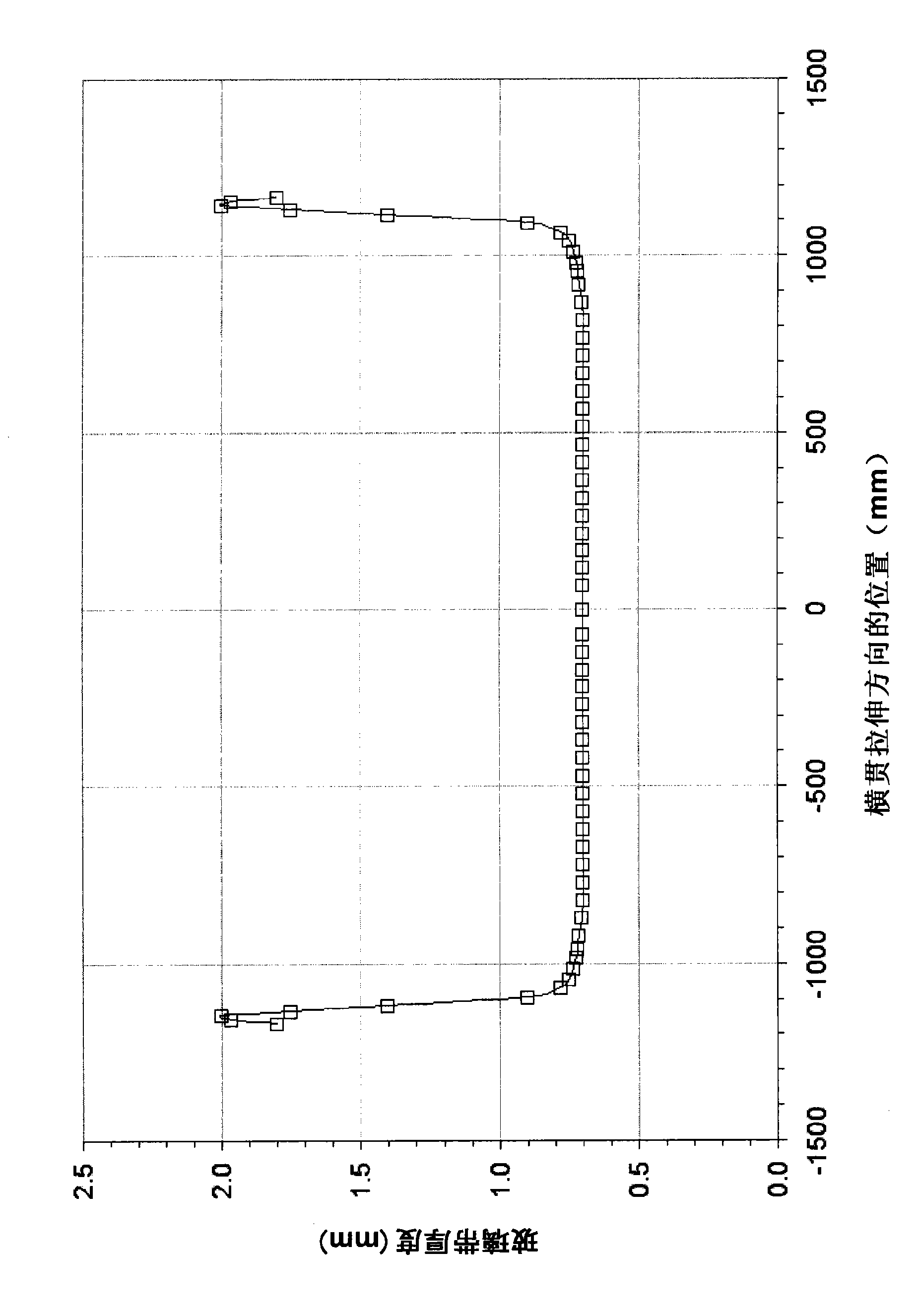
[0120] This example shows a uniform drop in temperature of the high hem during stretching to closely match the temperature nearby. (In this example and Examples 2-4, ρ·C p The v product is assumed to be 160kW / °K m 2 . ) Figure 10 The temperature distribution across the stretching direction without seam cooling (○ data points) and with seam cooling (□ data points) are compared. (In this and similar figures, the zero point corresponds to the centerline of the glass ribbon.) As can be seen from these two curves, the cooling provides a significantly flatter temperature distribution across the stretching direction.

[0121] Figure 11 and 12 are the temperature and heat flux distributions down the stretching direction for this example, where in each case ○ data points are for thickness equal to t b and without seam cooling across the stretch direction, □data points are for the same cross-draw position with seam cooling, ◇data points are for thickness equal to t q And for th...

example 2

[0125] This example shows insufficient non-uniform cooling of the high hem temperature during stretching. As in example 1, Figure 13 The temperature distribution across the stretching direction without seam cooling (○ data points) and with seam cooling (□ data points) are compared. It can be seen from these two curves that the cooling provides a significantly flatter temperature distribution across the stretching direction, but not as flat as in Example 1. In particular, the temperature at the thickest point of the bead is already substantially equal to the temperature in the adjacent good (or near good) region, but the temperature on either side of the thickest point is higher than the adjacent temperature . Figure 14 and 15 The temperature distribution down the stretching direction and the Q" distribution for this case are shown.

example 3

[0127] This example shows non-uniform supercooling of the high hem temperature during stretching. As in examples 1 and 2, Figure 16 The temperature distribution across the stretching direction without seam cooling (○ data points) and with seam cooling (□ data points) are compared. It can be seen from these two curves that in this case, without substantially flattening the temperature distribution across the direction of stretching, the distribution with cooling exhibits a temperature change of a magnitude similar to that without cooling The situation is similar, but with opposite signs. This distribution is useful when it is desired to introduce a shape or stress distribution in the glass ribbon opposite to that which would occur without cooling.

[0128] Figure 17 and 18 The temperature profile and Q" profile for the draw down for this case are shown. Since the added cooling is stronger in this case, when the crimp cooling is applied t q The temperature distribution at...


PUM


Abstract

Methods and apparatus for controlling the stress in, and the shape of, the glass ribbon (15) formed in a downdraw glass manufacturing process (e.g., the fusion downdraw process) are provided. In certain embodiments, the control is achieved by cooling the bead portions (21a, 21b) of the ribbon (15) at a rate which provides a heat flux Q''b at the thickest part of the bead (23a, 23b) which is given by Q''b=Q''q+[Delta]Q'', where (i) Q''q is the heat flux at a transverse position adjacent to the bead portion (21a, 21b) at which the ribbon's thickness equals 1.05*tcenter, where tcenter is the final thickness at the ribbon's center line (17), and (ii) [Delta]Q''>=(tb/tq-1)Q''q+10 kilowatts/meter2, where tb is the thickness of the thickest part of the bead portion. The cooling can take place along the entire length of the ribbon (15) or at selected locations, e.g., in the portion (50) of the draw which includes the glass transition temperature region (31) or the portion (60) of the draw where individual glass sheets (13) are cut from the ribbon (15).

Description

technical field [0001] The present application relates to the manufacture of glass sheets, such as glass sheets used as substrates in display devices such as liquid crystal displays (LCDs). More particularly, the present application relates to methods and apparatus for controlling stress and its shape in a glass ribbon from which the above-mentioned glass sheet is produced in a down-draw glass manufacturing process, such as a fusion down-draw process, and to Methods and apparatus for controlling stress and shape thereof in a formed glass sheet. Background technique [0002] Display devices are used in various applications. For example, thin-film-transistor liquid-crystal displays (TFT-LCDs) are used in notebook computers, desktop flat-panel monitors, LCD televisions, and Internet and communication equipment, among others. [0003] Many display devices, such as TFT-LCD panels and organic light-emitting diode (OLED) panels, are fabricated directly on a flat sheet of glass (g...

Claims


Application Information

Patent Timeline
IPC IPC(8): C03B17/06
CPCC03B17/067Y02P40/57
Inventor K·W·阿尼奥莱克S·R·伯德特L·R·德帕尔E·朴
Owner CORNING INC
Why Eureka
Try Eureka