Valve arrangement structure for cylinder head of air-cooled diesel engine

A technology of layout structure and cylinder head, which is applied in the direction of cylinder, cylinder head, air cooling, etc., can solve the problems of increased valve movement difference, cooling dead angle, and influence of cylinder head cooling effect, etc., so as to achieve the effect of motion balance and performance improvement

Active Publication Date: 2010-09-01
LONCIN MOTOR
View PDF5 Cites 2 Cited by
  • Summary
  • Abstract
  • Description
  • Claims
  • Application Information

AI Technical Summary

Problems solved by technology

This structure makes the solid part of the cylinder head between the intake valve and the exhaust valve, and the cooling air is formed from the cooling air passage to the intake valve to cool down the entity at the intake valve. However, due to the exhaust valve and the intake valve The intake valve is in a straight line, and the exhaust valve is located behind the intake valve. After the cooling air cools the intake valve, it bypasses the exhaust valve and flows out. Since the exhaust valve is behind the intake valve, the exhaust valve The surrounding area is almost a cooling dead zone, which cannot be effectively cooled, and the overall cooling effect of the cylinder head is seriously affected
As a result, the cooling of the intake and exhaust valves of the existing air-cooled diesel engine is uneven, the difference in valve movement increases, and the performance of the diesel engine is affected.

Method used


Image

  • Valve arrangement structure for cylinder head of air-cooled diesel engine
  • Valve arrangement structure for cylinder head of air-cooled diesel engine
  • Valve arrangement structure for cylinder head of air-cooled diesel engine

Examples


Embodiment Construction

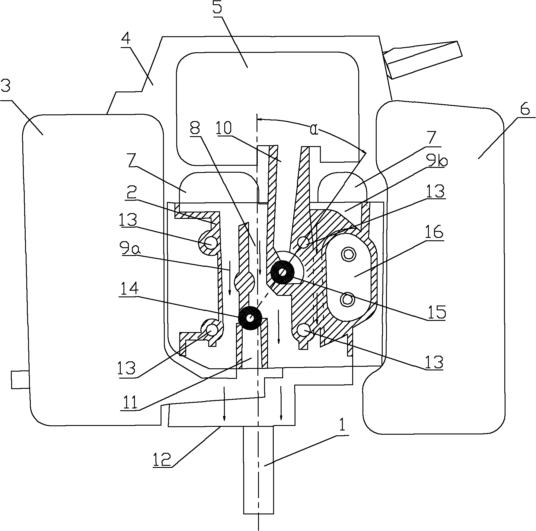
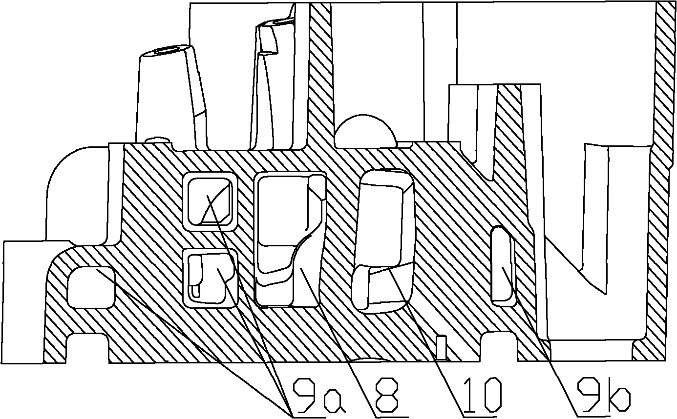
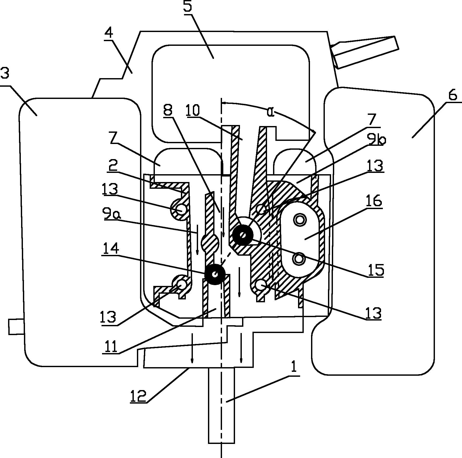
[0014] refer to figure 1 and figure 2 , air-cooled diesel engine cylinder head valve arrangement structure, diesel engine includes crankcase and cylinder head, cylinder head is installed above the crankcase, cylinder head 2 solid part is provided with a number of mounting holes, through the mounting holes through the connecting bolt 13 to put the cylinder head Connect and install with the crankcase. A crankshaft 1 is arranged in the crankcase, and the crankshaft 1 protrudes from the side of the crankcase. The muffler 3 is installed on the left side of the crankcase, the oil tank 6 is installed on the right side, and the starter 4 and the air filter 5 are installed on the upper side. 5 is located above the starter 4, and an air guide cover 7 is installed between the air filter 5 and the cylinder head 2, and the air guide cover 7 guides the cooling wind formed by the rotation of the wind wheel to the side of the cylinder head. Diesel engine cylinder head 2 has intake passage ...


PUM


Abstract

The invention relates to a valve arrangement structure for the cylinder head of an air-cooled diesel engine. The air inlet passage and the air outlet passage on the cylinder head of the diesel engine are respectively arranged on the two sides opposite to the cylinder head; the axial direction of the crankshaft of the diesel engine is the same as an air inlet / outlet direction; the central connecting line between an air inlet valve arranged on the air inlet passage and an air outlet valve arranged on the air outlet passage and the axial direction of the crankshaft are obliquely staggered to form an included angle; the cylinder head is provided with a plurality of cooling air passages, wherein a left cooling air passage runs through a left entity of the air outlet valve; a right cooling air passage runs through a right entity of the air inlet valve; an intermediate cooling air passage runs through an entity between the air inlet valve and the air outlet valve; and the air inlet end of the cooling passage corresponds to the air guide cover arranged on the diesel engine. By the valve arrangement structure for the cylinder head of the air-cooled diesel engine, the central connecting line between the air inlet valve and the air outlet valve and the axial direction of the crankshaft are obliquely staggered to form the included angle, the peripheries of the air inlet valve and the air outlet valve can be effectively cooled, not only the isostatic movement of the air inlet valve and the air outlet valve can be ensured, the performances of the diesel engine are improved, but also the integral cooling effect of the cylinder head can be improved.

Description

technical field [0001] The invention relates to the field of small air-cooled diesel engines, in particular to an air-cooled diesel engine cylinder head valve arrangement structure. Background technique [0002] Usually, the intake valve and exhaust valve of the cylinder head in a small air-cooled diesel engine are arranged along a straight line parallel to the axis of the crankshaft. The projections overlap, and the set cooling air duct passes through the intake valve. This structure makes the solid part of the cylinder head between the intake valve and the exhaust valve, and the cooling air is formed from the cooling air passage to the intake valve to cool down the entity at the intake valve. However, due to the exhaust valve and the intake valve The intake valve is in a straight line, and the exhaust valve is located behind the intake valve. After the cooling air cools the intake valve, it bypasses the exhaust valve and flows out. Since the exhaust valve is behind the in...

Claims


Application Information

Patent Timeline
Patent Type & Authority Applications(China)
IPC IPC(8): F02F1/42F02F1/28
CPCF02F1/28F02F1/4285F01P1/02
Inventor 景华阳刘荣利洪方平付强
Owner LONCIN MOTOR
Why Eureka
Try Eureka