

External sliding type expansion junction for contact rail
A technology of expansion joints and contact rails, applied in the direction of power rails, etc., can solve the problems of reduced electrical conductivity and unstable current carrying capacity, and achieve the effects of not easy to wear, long service life, and large contact area
- Summary
- Abstract
- Description
- Claims
- Application Information
AI Technical Summary
Problems solved by technology
Method used
Image

Examples
Embodiment 1
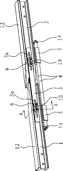
[0031] The joint is located between two contact rails 1 and 2 which are located on the same straight line and have an "I"-shaped cross section. One of the bottom and top surfaces of the two contact rails 1 and 2 is connected to the power receiving shoe. The front side is in contact, the other is the back side in contact with the electrical connector, the sides of the front side or the back side are the sides for installing the guide plate, and the distance between two adjacent contact rails depends on the longitudinal expansion and contraction of the two contact rails quantity.
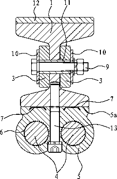
[0032] like figure 1 As shown, the outer sliding contact rail expansion joint mainly includes a guide plate 3 , a rigid guide rail 4 and an electrical connector 5 . Wherein, the guide plate 3 guides the expansion and contraction of the two contact rails 1 and 2. Since the length dimension of the contact rail is much larger than its width dimension, the expansion and contraction of the contact rail ma...
Embodiment 2
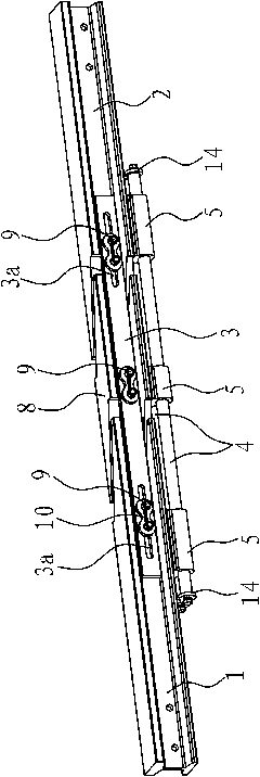
[0039] like image 3 As shown, the structure and principle of this embodiment are basically the same as those of Embodiment 1, the only difference being that there is also a piece at the interval between the first contact rail 1 and the second contact rail 2 which is in line with the two contact rails 1 and 2. The fixed rail 8, the fixed rail 8 has the same section shape as the contact rail 1 and the contact rail 2 2, but the length is much shorter than the contact rail 1 and the contact rail 2 2, and the middle part of the fixed rail 8 is connected with the guide plate 3 by the bolt 9 The phase is fixed, and the fixed rail 8 and the rigid guide rail 4 are also connected by an electrical connector 5, which is connected in the same way as the electrical connector 5 between the contact rail one 1 and the rigid guide rail 4. Since the fixed rail 8 is arranged between the two contact rails 1 and 2 in this structure, a space is reserved at both ends of the fixed rail 8. Obviously, ...
PUM
 Abstract
Description
Claims
Application Information