Automatic chain belt conveyor

A conveyor and chain belt technology, applied in the direction of conveyors, conveyor objects, conveyor control devices, etc., can solve the problems of inaccurate stop position of the transmission belt, unadjustable transmission speed of the transmission belt, and insufficient running of the transmission belt products, etc., to achieve control The effect of staying time, preventing product misoperation, and preventing product from being in place

Inactive Publication Date: 2010-09-08
覃其凤
View PDF4 Cites 9 Cited by
  • Summary
  • Abstract
  • Description
  • Claims
  • Application Information

AI Technical Summary

Problems solved by technology

[0002] Conveyors can reduce manpower and time for moving items, and can reduce manufacturing costs. Therefore, conveyors are widely used in various industries that need to transport items, such as ultrasonic machines, soldering machines, pad printing machines, oil spray guns And other supporting conveyors, although these conveyors can improve production efficiency, reduce manufacturing costs, improve quality, etc., these conveyors generally include: racks, driving wheels installed on the racks, driven wheels, driving wheels to rotate The speed-regulating motor and the driving wheel drive the passive wheel to rotate through a transmission belt, but these conveyors have certain deficiencies: the products on the transmission belt will vibrate, the conveying speed of the transmission belt cannot be adjusted, the products on the transmission belt do not run in place, and the products on the transmission belt It will malfunction, the product stop position of the transmission belt is inaccurate, and the product residence time of the transmission belt cannot be adjusted, so it cannot meet the market demand

Method used


Image

  • Automatic chain belt conveyor
  • Automatic chain belt conveyor

Examples


Embodiment Construction

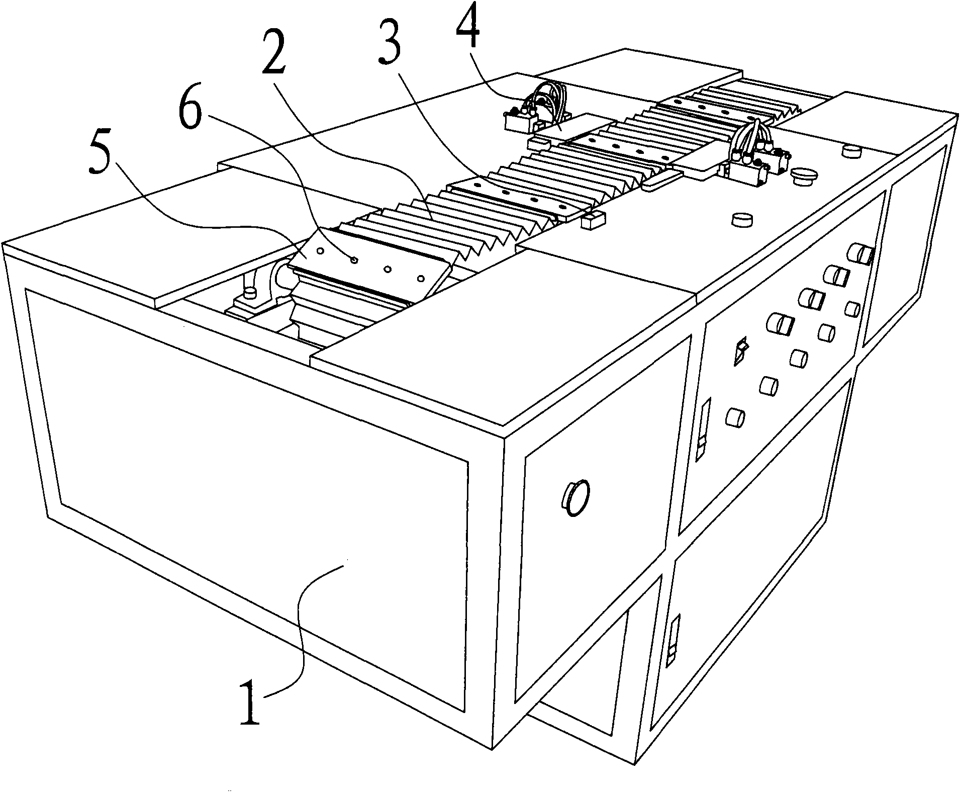
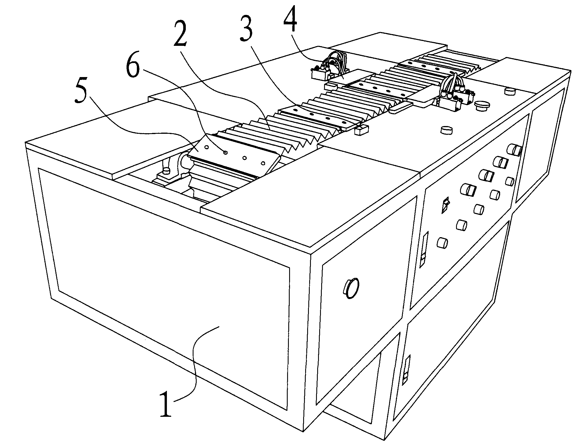
[0012] See figure 1 As shown, the present invention includes: a frame 1, a driving wheel installed on the frame 1, a driven wheel, a speed-regulating motor for driving the driving wheel to rotate, an induction switch 3, a timer, and a control circuit, wherein the speed-regulating motor, the induction switch 3. The timers are respectively connected with the control circuit.

[0013] Specifically: the above-mentioned driving wheel drives the driven wheel to rotate through a transmission belt 2, the driving wheel and the driven wheel are respectively the main sprocket and the driven sprocket, and the transmission belt 2 is a chain belt. Eight supporting plates 5 are installed on the transmission belt 2, and four positioning screw holes 6 are respectively arranged on these supporting plates 5, and various types of clamps or bottom molds can be conveniently installed on the supporting plates 5 through these positioning screw holes 6. .

[0014] Above-mentioned timer can control t...


PUM


Abstract

The invention relates to the technical field of conveyors, in particular to an automatic chain belt conveyor. The automatic chain belt conveyor comprises a frame, a driving wheel, a driven wheel, and a speed regulation motor which drives the driving wheel to rotate, wherein the driving wheel, the driven wheel and the speed regulation motor are arranged on the frame, the driving wheel drives the driven wheel to rotate via a transmission belt. The automatic chain belt conveyor also comprises an inductive switch, a timer and a control circuit, wherein the speed regulation motor, the inductive switch and the timer are respectively and electrically connected with the control circuit. The invention can prevent the product on a supporting plate from vibrating, can adjust the conveyance speed of the supporting plate, can prevent the misplacing of the product, can prevent the false operation of the product, can realize accurate stop position of the supporting plate, can control the stop time of the supporting plate, and can operate fully automatically by being matched with an ultrasonic machine, a soldering machine, a transfer printing machine, an oiling gun and other mechanical devices. In addition, the invention has firm overall structure and can be moved freely.

Description

Technical field: [0001] The invention relates to the technical field of conveyors, in particular to an automatic chain-belt conveyor. Background technique: [0002] Conveyors can reduce manpower and time for moving items, and can reduce manufacturing costs. Therefore, conveyors are widely used in various industries that need to transport items, such as ultrasonic machines, soldering machines, pad printing machines, oil spray guns And other supporting conveyors, although these conveyors can improve production efficiency, reduce manufacturing costs, improve quality, etc., these conveyors generally include: racks, driving wheels installed on the racks, driven wheels, driving wheels to rotate The speed-regulating motor and the driving wheel drive the passive wheel to rotate through a transmission belt, but these conveyors have certain deficiencies: the products on the transmission belt will vibrate, the conveying speed of the transmission belt cannot be adjusted, the products on...

Claims


Application Information

Patent Timeline
Patent Type & Authority Applications(China)
IPC IPC(8): B65G17/00B65G17/12B65G17/42B65G23/06B65G43/00
Inventor 覃其凤
Owner 覃其凤
Why Eureka
Try Eureka