Machine head and machine tail centralized lubricating system of belt conveyor

A belt conveyor, centralized lubrication technology, applied in the direction of conveyor objects, transportation and packaging, cleaning devices, etc., can solve the problems of low lubrication efficiency, uneven lubrication, discontinuous lubrication, etc., to improve lubrication efficiency and oil circuit layout And the effect of easy installation and easy operation

Inactive Publication Date: 2010-09-08
SHAANXI PUBAI SANTONG
View PDF6 Cites 6 Cited by
  • Summary
  • Abstract
  • Description
  • Claims
  • Application Information

AI Technical Summary

Problems solved by technology

[0003] The technical problem to be solved by the present invention is to provide a centralized lubrication system for the head and tail of the belt conveyor in view of the deficiencies in the above-mentioned prior art, which has reasonable design, simple operation, safe and reliable work, good lubrication effect and can realize Multiple lubricating points are used for centralized lubrication, which effectively overcomes the defects and deficiencies of existing lubrication methods such as uneven lubrication, discontinuity, poor lubrication reliability, and low lubrication efficiency.

Method used


Image

  • Machine head and machine tail centralized lubricating system of belt conveyor
  • Machine head and machine tail centralized lubricating system of belt conveyor
  • Machine head and machine tail centralized lubricating system of belt conveyor

Examples


Embodiment 1

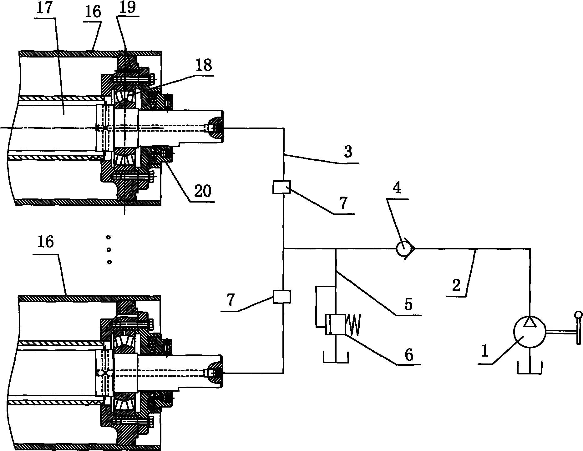
[0031] Such as figure 1 As shown, the present invention includes a main oil supply pipeline 2, a lubricating pump that continuously injects the lubricating grease in the oil storage tank into the main oil supply pipeline 2, a check valve 4 installed on the main oil supply pipeline 2, and respectively connected with the main oil supply pipeline. A plurality of oil supply branches 3 connected to the oil outlets of 2, a plurality of oil supply distributors 7 respectively installed on the plurality of oil supply branches 3, an oil return pipeline 5 communicated with the main oil supply pipeline 2 and installation The overflow valve 6 on the oil return line 5, the oil inlet of the main oil supply line 2 is connected to the oil filling port of the lubricating pump, and the oil outlets of a plurality of oil supply branches 3 are connected to the head of the belt conveyor. The lubricating parts required to be lubricated at the rear of the machine are connected, and the oil outlet of t...

Embodiment 2

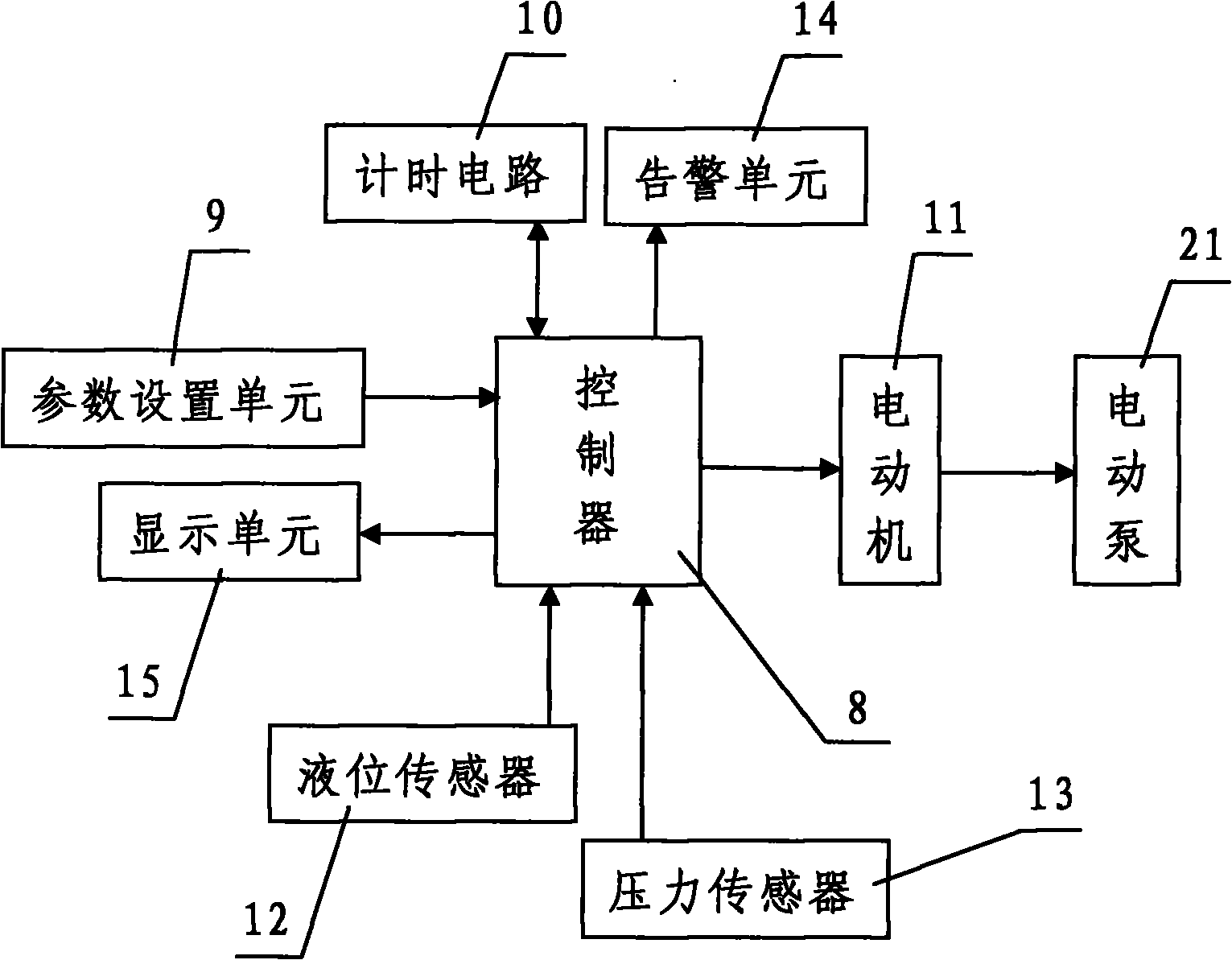
[0035] Such as figure 2 As shown, in this embodiment, the difference from Embodiment 1 is that the lubricating pump is an electric pump 21 driven by a motor 11, and also includes a controller 8 and a parameter setting unit 9 respectively connected to the controller 8 and timing circuit 10 , the controller 8 is connected to the motor 11 and the motor 11 is connected to the electric pump 21 . in addition. The present invention also includes a liquid level sensor 12 for real-time detection of the oil level in the oil storage tank, a pressure sensor 13 for real-time detection of the oil supply pressure inside the main oil supply pipeline 2, and a sensor connected to the controller 8. The alarm unit 14 , the liquid level sensor 12 and the pressure sensor 13 are both connected to the controller 8 , and also includes a display unit 15 connected to the controller 8 . In this embodiment, the structures, connections and working principles of other parts are the same as those in Embod...


PUM


Abstract

The invention discloses a machine head and machine tail centralized lubricating system of a belt conveyor, comprising a main oil supply pipeline, a lubricant pump, a one-way valve, a plurality of oil supply branches, a plurality of oil feed distributors, an oil return pipeline and an overflow valve, wherein the lubricant pump continuously injects lubricating grease inside an oil storage tank into the main oil supply pipeline; the one-way valve is arranged on the main oil supply pipeline; the plurality of oil supply branches are respectively connected with an oil outlet of the main oil supply pipeline; the plurality of oil feed distributors are respectively arranged on the plurality of oil supply branches; the oil return pipeline is communicated with the main oil supply pipeline; the overflow valve is arranged on the oil return pipeline; an oil inlet of the main oil supply pipeline is connected with an oil injection orifice of the lubricant pump; the oil outlets of the plurality of oil supply branches are connected with the lubricating positions of the machine head and the machine tail of the belt conveyor, wherein the lubricating positions need to be lubricated; and the oil outlet of the oil return pipeline is connected into the oil storage tank. The invention has the advantages of reasonable design, easy operation, safe and reliable work and good lubricating effect, can also realize the centralized lubrication of a plurality of lubricating points and effectively overcomes the defects and the shortages of nonuniform and discontinuous lubrication, poor lubricating reliability, low lubricating efficiency, and the like of the traditional lubrication mode.

Description

technical field [0001] The invention relates to an oil lubricating system, in particular to a centralized lubricating system for the head and tail of a belt conveyor. Background technique [0002] Nowadays, when lubricating the parts that need to be lubricated at the head and tail of the belt conveyor used in coal mines, most of them use distributed lubrication or manual lubrication. However, in the actual use process, the above two lubrication methods have various defects and shortcomings such as complicated operation, intermittent lubrication, high labor intensity, and low efficiency, and cannot meet the requirements of the lubricating grease required for the head and tail of the belt conveyor. The actual requirements of injection volume and injection frequency, so the reliability is not high. Contents of the invention [0003] The technical problem to be solved by the present invention is to provide a centralized lubricating system for the head and tail of the belt con...

Claims


Application Information

Patent Timeline
Patent Type & Authority Applications(China)
IPC IPC(8): B65G45/02
Inventor 李耀辉曹保新田方程永军李祖洲
Owner SHAANXI PUBAI SANTONG
Why Eureka
Try Eureka