Concrete mixing pump

A technology for concrete pumps and mixers, which is applied in construction, building structure, construction material processing, etc., can solve the problems affecting the convenience of feeding at the feed port of the mixer, affecting the service life, shortening the service life, etc., achieving good ventilation, reducing Loss, the effect of reducing requirements

Inactive Publication Date: 2010-09-08
安良平
View PDF4 Cites 2 Cited by
  • Summary
  • Abstract
  • Description
  • Claims
  • Application Information

AI Technical Summary

Problems solved by technology

During normal operation, since the cement in the mixer is the main source of dust pollution, it is easy to cause the power system or hydraulic system installed close to the mixer to be polluted by cement and cause various problems, affecting its service life. Secondly, it also affects the mixer. The feeding port is convenient
Referring to the patent application No. 95225163.9, a fully automatic concrete mixer is disclosed. The motor of this patent is directly arranged at the rear and lower part of the feeder. The dust during feeding can easily pollute the motor and shorten its service life.

Method used


Image

  • Concrete mixing pump
  • Concrete mixing pump
  • Concrete mixing pump

Examples


Embodiment 1

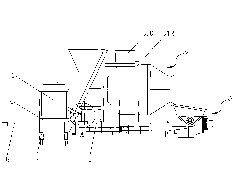
[0025] Such as figure 1 A mixing concrete pump shown includes a frame 1, a mixer 2 fixedly arranged at the front end of the frame 1, a pumping mechanism 3 arranged at the lower part of the frame 1, and a pumping mechanism 3 arranged on the frame 1, which is located at the rear of the mixer 2. Bracket 6, the power unit 4 that drives the mixer 2 and the pumping mechanism 3, the power unit 4 is fixedly arranged on the power bracket 6, wherein the power unit 4 can be a motor or a diesel engine. A door-shaped support 12 is also installed on the top of the mixer 2, and a hydraulic oil tank 10 is arranged between the door-shaped support 12 and the frame 1. In addition, a hydraulic pump 11 is also provided on the power support 6, such as Figure 4 shown.

[0026] The rear end of the frame 1 is detachably and adornably connected with a traction frame 5 , and in this embodiment the traction frame 5 is connected with the frame 1 through a latch 8 . The power bracket 6 is erected on the...

Embodiment 2

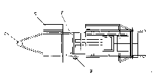
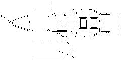
[0030] Such as Figure 6 , 7 As shown: in this embodiment, the frame 1 is provided with a track 17, the power support 6 is provided with a guide rail 18, the power support 6 is arranged on the track 17 through the guide rail 18, and a linear bearing 19 is installed between the track 17 and the guide rail 18 , the linear bearing 19 can be replaced by rollers, needle rollers or wear-reducing pads, so that the guide rail 18 can slide on the track 17, reducing the resistance of the power support 6 sliding to the mixer 2 side. Before the mixing concrete pump is used, the power bracket 6 is positioned at the rear of the mixer 20 (such as Figure 8 shown); when needing to work, the guide rail 18 of the power support 6 slides to one side of the mixer 2 along the track 17, and is fixed by a fixing bolt to start normal work (as Figure 9 shown). After the work is finished, the fixing bolts are disassembled, and the power support is slid to the rear part of the mixer 2 along the track...


PUM


Abstract

The invention relates to a concrete mixing pump. The concrete mixing pump comprises a rack, a stirrer fixed on the front end of the rack, a pumping mechanism arranged on the lower part of the rack, a powered support which is arranged on the rack and positioned on the lower part of the stirrer, a drive stirrer and a power unit of the pumping mechanism, wherein the power unit is fixed on the powered support, the powered support is movably arranged on the rack; when the concrete mixing pump is in the working state, the powered support moves to one side of the stirrer; and when the concrete mixing pump is in the ready state, the powered support moves to the back of the stirrer. The preparation time for the movement of the concrete mixing pump of the invention is reduced; when the power unit on the powered support is used, the power unit is rotated to one side of the stirrer so as to have good ventilation, be far from the stirrer-the pollutant source and reduce the wear and tear of the machine; and when the concrete mixing pump is in the transport state, the power unit is rotated to the back of the stirrer so that the lateral dimension of complete machine is reduced, the demand on road surface and place is lowered, and the concrete mixing pump can better adapt to transport on narrow roads.

Description

technical field [0001] The invention relates to a mixing concrete pump. Background technique [0002] At present, in the process of housing construction, with the improvement of the anti-seismic requirements of the housing, more and more buildings are cast-in-situ with the number of floors below six. The prior art solution is to use a mixer for batching and a concrete pump to pump the concrete. [0003] In order to facilitate transportation, the mixer and concrete pump are usually assembled on the same equipment, and this type of mixing concrete pump is generally used in small construction sites, which often have narrow transportation roads and are constructed by small construction teams, which requires mixing Concrete pumps must be small in size, which is convenient for small vehicles to transport on narrow roads. Therefore, the power system or hydraulic system driving the mixing concrete pump is installed near the feed inlet of the mixer. During normal operation, since ...

Claims


Application Information

Patent Timeline
IPC IPC(8): E04G21/02
Inventor 安良平
Owner 安良平
Why Eureka
Try Eureka