Dual-polarized antenna structure, antenna housing and designing method thereof

A dual-polarized antenna and radome technology, applied to antennas, electrical components, etc., can solve problems such as high cost, reduced antenna size, and difficult maintenance of base station lines

Inactive Publication Date: 2010-09-08
IND TECH RES INST
View PDF1 Cites 55 Cited by
  • Summary
  • Abstract
  • Description
  • Claims
  • Application Information

AI Technical Summary

Problems solved by technology

However, the above-mentioned technologies will encounter the following disadvantages in practical application: 1. The signal loss of the feeding network is greatly increased; 2. The design of the feeding network is complicated; 3. The overall volume of the antenna becomes larger; The antenna gain cannot be effectively increased, the maintenance of base station lines is difficult and expensiv

Method used


Image

  • Dual-polarized antenna structure, antenna housing and designing method thereof
  • Dual-polarized antenna structure, antenna housing and designing method thereof
  • Dual-polarized antenna structure, antenna housing and designing method thereof

Examples


Embodiment Construction

[0049] In order to fully understand the features and effects of the present invention, the present invention will be described in detail through the following specific implementation examples and in conjunction with the accompanying drawings, as follows:

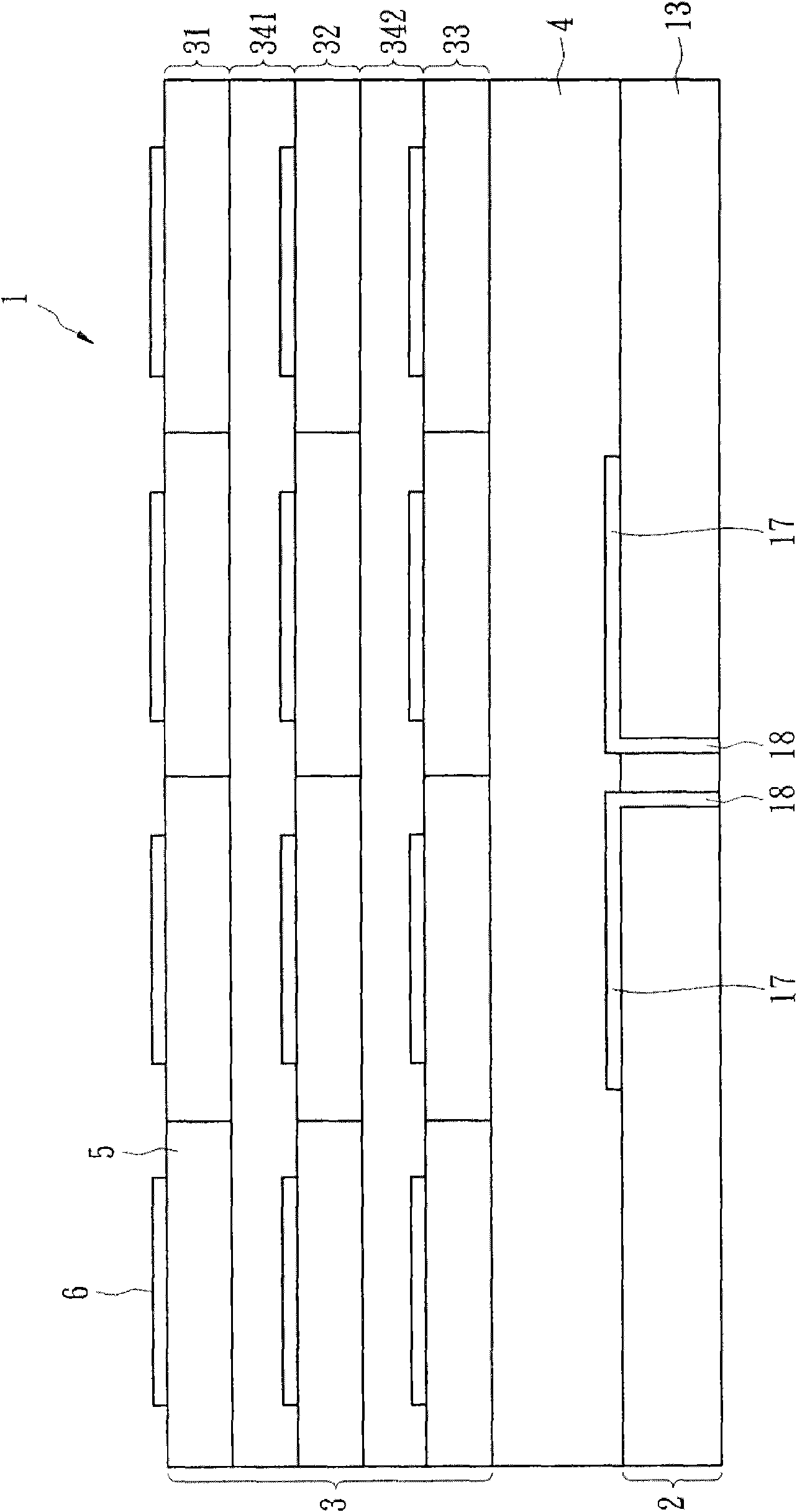
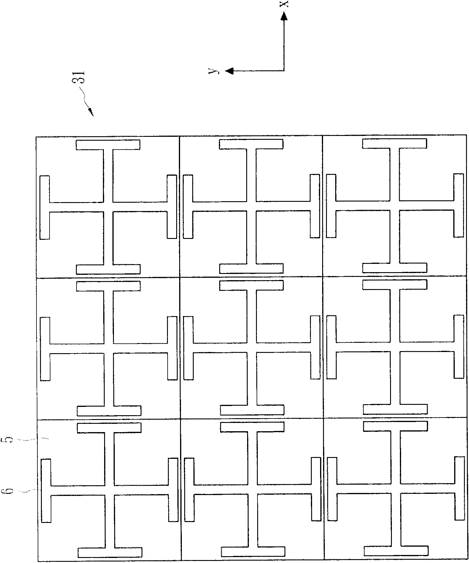
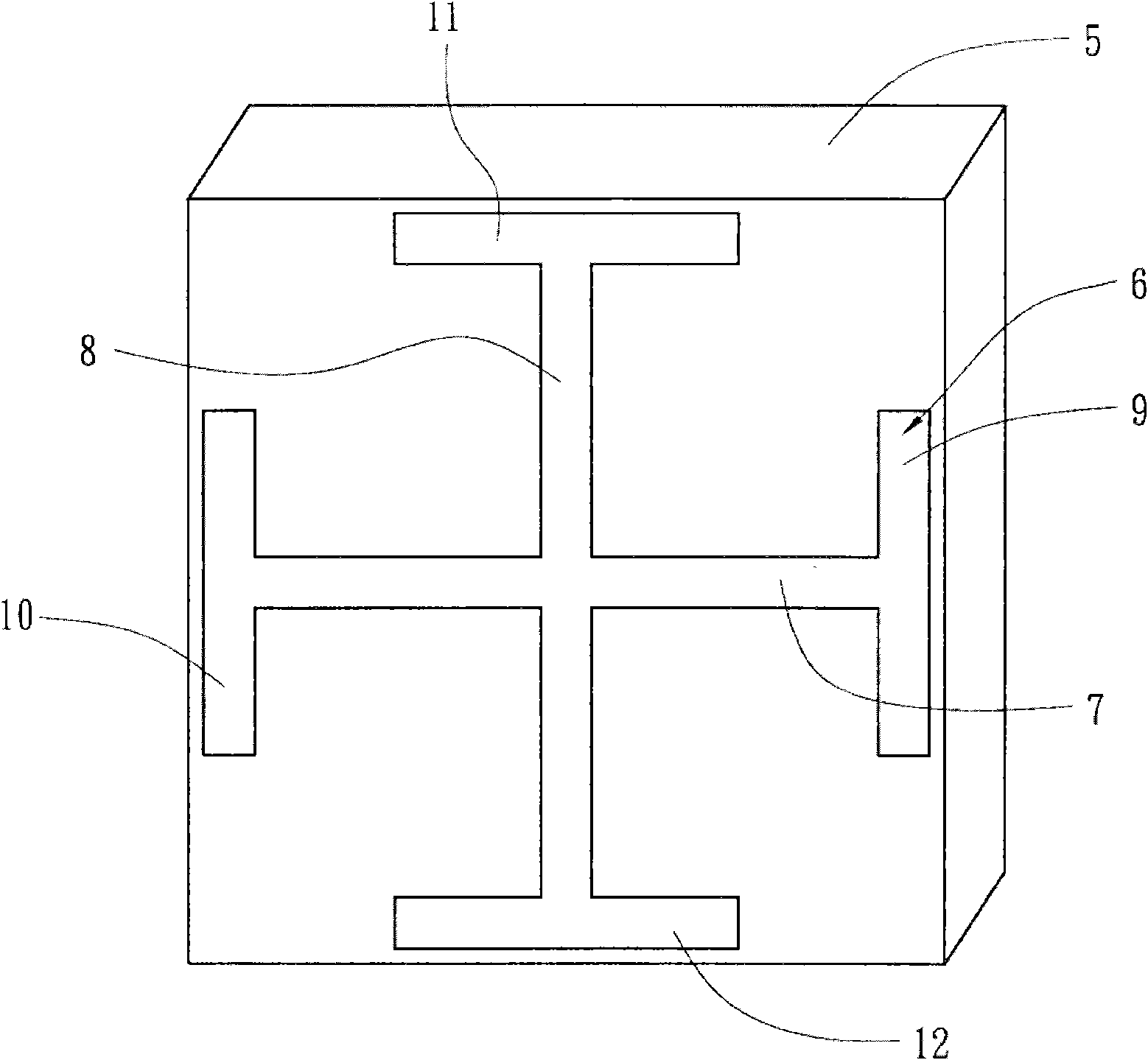
[0050] figure 1 A side sectional view of a dipolar antenna structure 1 according to an embodiment of the present invention is shown. The dual-polarized antenna structure 1 includes an antenna 2 , at least one dielectric substrate layer 4 and a radome 3 . Wherein the distance between the antenna 2 and the radome 3 is less than or equal to 0.1 times the wavelength corresponding to the operating frequency.

[0051] The radome of the present invention does not have the restriction that the Fabry Perot antenna must include a ground plane, so the following uses a dipole antenna as an example for illustration. The antenna 2 is a dipole antenna, which includes two radiation conductors 17 disposed on the surface of the substrate 13...


PUM


Abstract

The invention discloses a dual-polarized antenna structure, an antenna housing and a designing method thereof. The dual-polarized antenna housing comprises multiple layers of medium substrates, wherein a plurality of metal patterns arranged in an array mode are arranged on the surface of each medium substrate, and are not changed in the patterns which are rotated at 90 degrees around the axle center vertical to the medium substrate.

Description

technical field [0001] The invention relates to a dual-polarization antenna structure, a radome and a design method thereof, in particular to an antenna which can increase the gain of the antenna. Background technique [0002] The essential component of the wireless communication system is the front-end circuit antenna, whose characteristics are related to the signal quality of the entire system. In general, the received signal strength is determined by the following formula: [0003] P R = P t × e t e r × D t D r × λ 2 ( 4 πr ) [0004] Among them, P R is the receiving power at the receiving end, P t is the transmit power of the transmitter...

Claims


Application Information

Patent Timeline
IPC IPC(8): H01Q15/02
Inventor 林弘萱吴俊熠林根煌苏欣龙黄宏祺
Owner IND TECH RES INST
Why Eureka
Try Eureka