
CCD Light Source Intensity Adaptive Adjustment System and Method

A technology of adaptive adjustment and light source intensity, which is applied in the direction of light source, electric light source, TV system components, etc. It can solve the problems that the light source intensity cannot be automatically judged and adjusted automatically, the light source intensity is difficult to achieve linear change, and difficult to adjust to the expected value. , to meet the requirements of automatic adjustment of light source intensity, stable light source control parameters, and high adjustment efficiency

Inactive Publication Date: 2011-12-28
SOUTH CHINA UNIV OF TECH
View PDF0 Cites 0 Cited by
  • Summary
  • Abstract
  • Description
  • Claims
  • Application Information

AI Technical Summary

Problems solved by technology

However, in the existing image detection system, the light source intensity cannot be automatically judged and adjusted by the computer, and the light source intensity can only be manually adjusted according to the operator’s subjective visual judgment and feedback on the light source intensity to obtain the product image under the desired light source intensity, so that possible and easily discernable by the human eye
When the computer is used for automatic identification of products, the manual adjustment of the light source brings a series of problems. First, the work efficiency is low. Recognition also needs to adjust the light source, so that the automatic process has to participate in manual operation; secondly, the stability is poor. Usually, the automatic recognition process has a consistent requirement for image brightness, and manual adjustment is affected by subjective factors and operating techniques. Make the product undetectable
[0003] The traditional light source intensity adjustment uses a small current thyristor dimming circuit, which uses the change of the conduction angle of the thyristor to achieve dimming, so it is difficult to achieve when the light source intensity requires strict linear output
Moreover, the traditional light source intensity adjustment is completed by manually rotating or toggling the potentiometer. Due to the structure of the potentiometer, it is difficult to achieve a linear change in the light source intensity during the adjustment process, and it can only be recognized by the human eye within a general range.

Method used


Image

  • CCD Light Source Intensity Adaptive Adjustment System and Method
  • CCD Light Source Intensity Adaptive Adjustment System and Method
  • CCD Light Source Intensity Adaptive Adjustment System and Method

Examples


Embodiment

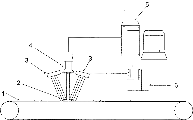
[0053] like figure 1 As shown, this CCD light source intensity self-adaptive adjustment system comprises upper computer 5, lower computer 6, light source 3 and CCD camera 4, and described light source 3, lower computer 6, upper computer 5 and CCD camera 4 are connected successively by connection line; The upper computer 5 is provided with a light source intensity analysis system, and the lower computer 6 is provided with a light source intensity adjustment control system.

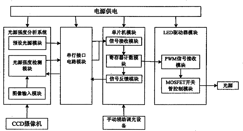
[0054] like figure 2 As shown, the light source intensity analysis system includes a preset light source module, an image input module and a light source intensity detection module, the image input module is connected to the CCD camera 4, and the image input module is connected to the light source intensity detection module , the preset light source module and the light source intensity detection module are respectively connected to the light source intensity adjustment control system in the lower compute...


PUM


Abstract

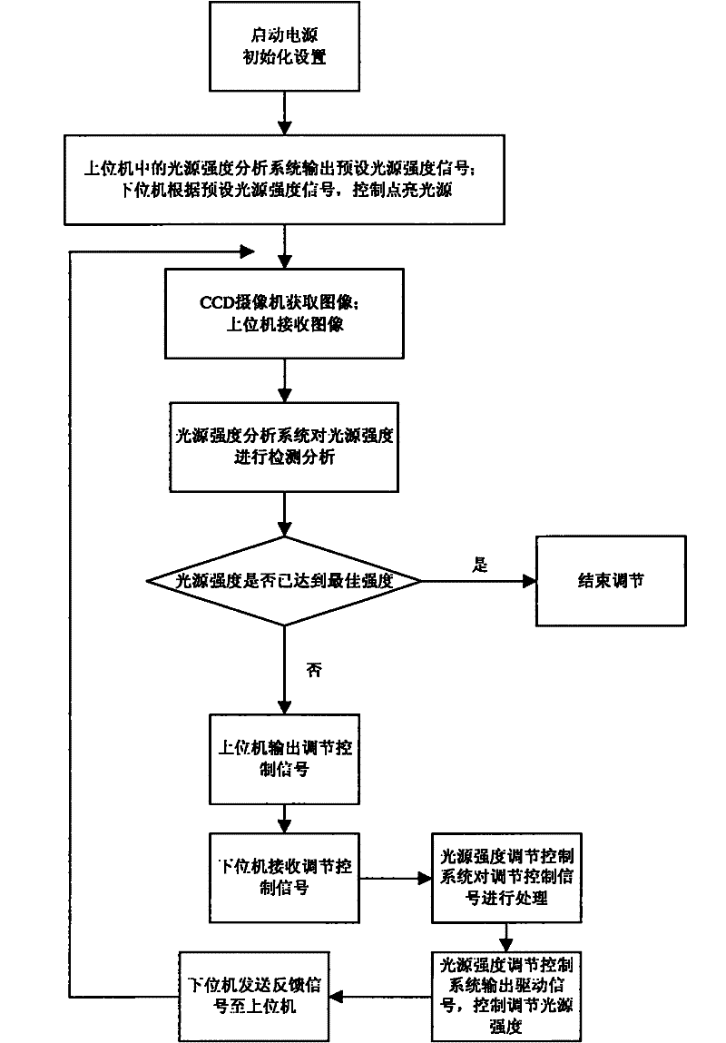
The invention provides a CCD light source intensity self-adaptive adjustment system, comprising an upper computer, a lower computer, a light source and a CCD camera, wherein the light source, the lower computer, the upper computer and the CCD camera are sequentially connected by connecting wires; the upper computer is provided with A light source intensity analysis system, the lower computer is provided with a light source intensity adjustment control system. The present invention also provides a method implemented by the above system, comprising the steps of: initializing settings; outputting a preset light source intensity signal, and controlling the lighting of the light source; a CCD camera acquires an image of the illumination intensity of the light source and transmits it to a host computer; the intensity of the light source The analysis system detects and analyzes the intensity of the light source, and outputs an adjustment control signal; the lower computer controls the light source and adjusts the intensity of the light source according to the adjustment control signal. The invention can perform automatic feedback control and adjust the intensity of the light source according to the image, realize the self-adaptive adjustment of the intensity of the light source, and has the advantages of intelligence, high adjustment efficiency and good effect.

Description

technical field [0001] The invention relates to light source intensity adjustment technology, in particular to an adaptive adjustment system and method for acquiring images through a CCD camera and adaptively adjusting the light source intensity of the CCD. Background technique [0002] At present, the image detection system is often used for quality inspection in product production, that is, through light source irradiation, the image of the product is obtained for product inspection and analysis. In the existing image detection system, the CCD camera needs to obtain images suitable for human eyes or computer analysis and recognition under suitable and stable lighting conditions. However, in the existing image detection system, the light source intensity cannot be automatically judged and adjusted by the computer, and the light source intensity can only be manually adjusted according to the operator’s subjective visual judgment and feedback on the light source intensity to ...

Claims


Application Information

Patent Timeline
Patent Type & Authority Patents(China)
IPC IPC(8): H04N5/238H05B37/02
Inventor 黄茜叶家和
Owner SOUTH CHINA UNIV OF TECH
Learn More