Single-sided self-piercing friction stub rivet welding device and connection method thereof

A stud and self-piercing technology, applied in welding equipment, non-electric welding equipment, other manufacturing equipment/tools, etc., can solve the problems of reduced riveting force, reduced corrosion resistance of joints, complex process, etc., and achieve the effect of improving connection strength

Inactive Publication Date: 2010-09-15
SHANGHAI JIAO TONG UNIV
View PDF6 Cites 32 Cited by
  • Summary
  • Abstract
  • Description
  • Claims
  • Application Information

AI Technical Summary

Problems solved by technology

However, this prior art can only be used for the connection of thin plates and thick plates in order to prevent the deformation of the lower plate or pipe fittings because the riveting force is too large
At the same time, this method needs to use two kinds of equipment, self-piercing riveting and resistance spot welding, the process is complicated and the cost is extremely high, and it cannot be applied in large-scale production
[000...

Method used


Image

  • Single-sided self-piercing friction stub rivet welding device and connection method thereof
  • Single-sided self-piercing friction stub rivet welding device and connection method thereof
  • Single-sided self-piercing friction stub rivet welding device and connection method thereof

Examples


Embodiment 1

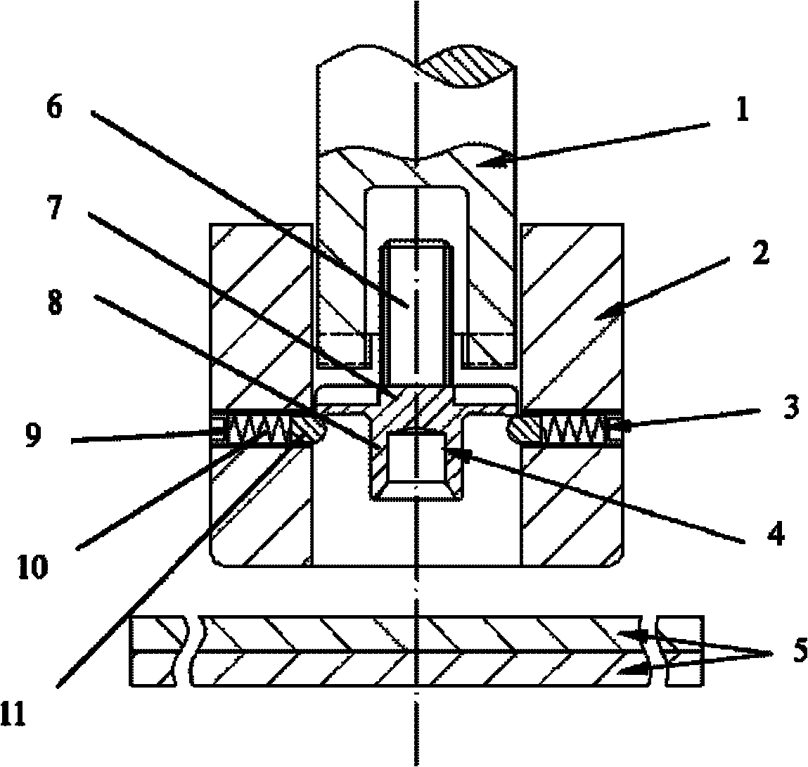
[0036] Such as figure 1 As shown, this embodiment includes: a driving sleeve rod 1, a positioning guide sleeve 2, a spring 10, a bead 11, a positioning mechanism 3, and a semi-hollow self-piercing stud rivet 4, wherein: the positioning guide sleeve 2 is sequentially socketed and driven from top to bottom The sleeve rod 1 and the semi-hollow self-piercing stud rivet 4, the spring 10, the beads 11 and the positioning mechanism 3 are horizontally distributed in the positioning guide sleeve 2 along the circumferential direction, the semi-hollow self-piercing stud rivet 4 is facing the driving sleeve rod 1, and the workpiece to be connected 5 is fixed below the semi-hollow self-piercing stud rivet 4 through the distal clamping mechanism.

[0037] The internal diameter of the positioning guide sleeve 2 is 12 mm, the external diameter is 24 mm, and there are 4 threaded holes of φ2.4 mm evenly distributed along the circumference at 6 mm from the lower end surface of the positioning gu...

Embodiment 2

[0058] The workpiece 5 used in this embodiment is: aluminum alloy AA6061-T6+high-strength steel DP590, that is, the aluminum alloy is on top, the low-carbon steel is on the bottom, and the thickness of the workpiece is matched: 2mm+1.2mm.

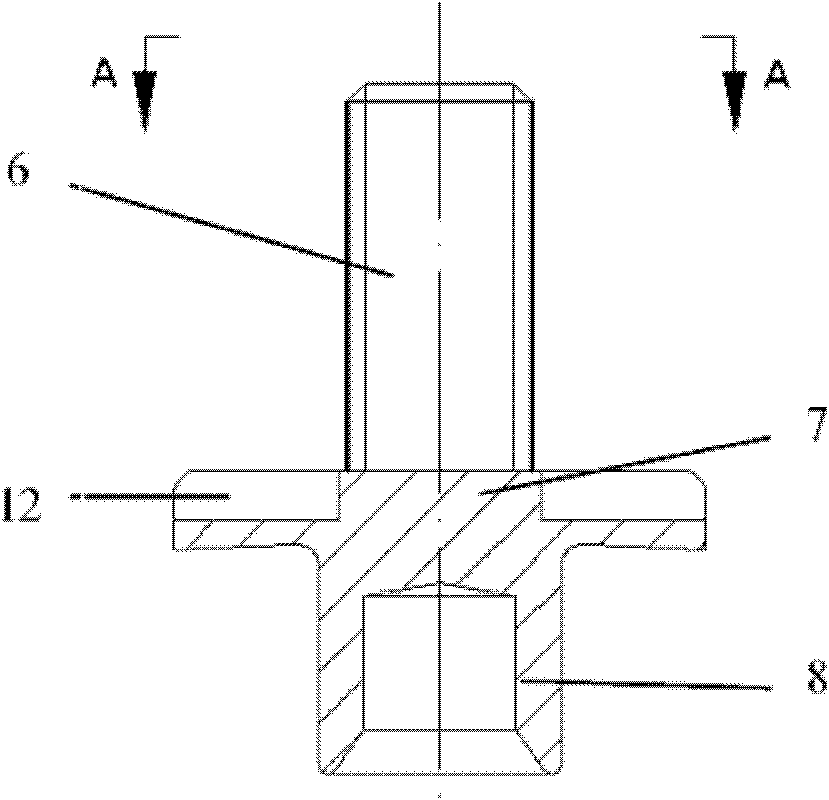
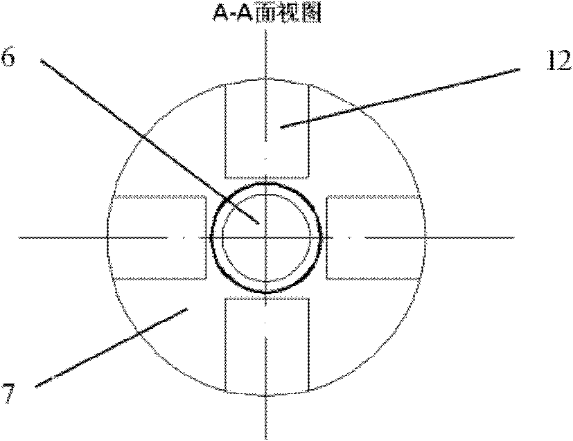
[0059] The semi-hollow self-piercing stud rivet 4 is made of high-strength boronized steel, the nominal diameter of the stud rod 6 is 4mm, the length is 12mm, the diameter of the flange 7 is 11.6mm, and the thickness, outer diameter and length of the screw leg 8 are 0.95 mm, 5mm and 4.5mm.

[0060] The surface of the semi-hollow self-piercing stud rivet 4 is coated with a zinc-tin alloy coating with a thickness of 13 μm, so as to realize the solid-phase connection between the contact interfaces between the screw leg 8 and the workpiece 5 .

[0061] Process parameters: The rotation speed of the driving sleeve rod 1 and the semi-hollow self-piercing stud 4 during the meshing stage is 60rpm, and the feed speed is 10mm / min; during the riveting ...


PUM

PropertyMeasurementUnit
The inside diameter ofaaaaaaaaaa
Outer diameteraaaaaaaaaa
Depthaaaaaaaaaa

Abstract

The invention discloses a single-sided self-piercing friction stub rivet welding device in the technical field of automobile manufacture, which comprises a drive loop bar, a positioning guide sleeve, a positioning mechanism and a semi-hollow self-piercing stub rivet, wherein the drive loop bar and the semi-hollow self-piercing stub rivet are sequentially sleeved in the positioning guide sleeve from top to bottom; the positioning mechanism is horizontally distributed in the positioning guide sleeve along a circumferential direction; the semi-hollow self-piercing stub rivet is arranged over against the drive loop bar; and a workpiece to be connected is fixed below the semi-hollow self-piercing stub rivet through a far-end clamping mechanism. In the invention, the semi-hollow self-piercing stub rivet is enabled to move in an axial direction and simultaneously rotate at a high speed in the circumferential direction. In the invention, by adopting friction heat generated by the high-speed rotation of the semi-hollow self-piercing stub rivet to soften the materials of non-ferrous alloys or dead-hard steel and the like, the plasticity of a riveted material is improved, the riveting force in the process of riveting the dead-hard steel is greatly decreased, an upper workpiece and a lower workpiece are cut off through the stub rivet to form mechanical self-locking connection, and the solid phase connection between the rivet and the riveted material is formed through the friction heat generated by the high-speed rotation of the rivet.

Description

technical field [0001] The invention relates to a device and method in the technical field of automobile manufacturing, in particular to a unilateral self-piercing friction stud riveting and welding device and a connection method thereof. Background technique [0002] Arc stud welding is a commonly used unilateral connection method in the assembly of steel automobile bodies. Its connection principle is that one end of the stud is in contact with the surface of the plate (or pipe), and the arc is energized. After the contact surface is melted, the stud is welded. A certain pressure is used to press it into the molten pool to finally complete the welding method. As a one-sided joining process, arc stud welding has great advantages and can be welded in narrow and deep spatial areas. With the development of the lightweight trend of automobile bodies, lightweight materials such as non-ferrous alloys and high-strength steels are increasingly favored by major automobile manufactur...

Claims


Application Information

Patent Timeline
IPC IPC(8): B23P23/04B21J15/10B23K20/12
CPCB21J15/027B21J15/025
Inventor 李永兵林忠钦楼铭来新民陈关龙金鑫
Owner SHANGHAI JIAO TONG UNIV
Why Eureka
Try Eureka