Pressure plate automatic translation clamping machine

A technology of clamping machine and pressing plate, applied in clamping, workpiece clamping device, metal processing machinery parts, etc., to achieve the effect of stable performance, simple structure and satisfactory accuracy

Inactive Publication Date: 2010-09-15
CITIC DICASTAL
View PDF4 Cites 38 Cited by
  • Summary
  • Abstract
  • Description
  • Claims
  • Application Information

AI Technical Summary

Problems solved by technology

The unclamping process is the opposite of the clamping process

Method used


Image

  • Pressure plate automatic translation clamping machine
  • Pressure plate automatic translation clamping machine
  • Pressure plate automatic translation clamping machine

Examples


Embodiment Construction

[0010] The details and working conditions of the specific device proposed according to the present invention will be described in detail below in conjunction with the accompanying drawings.

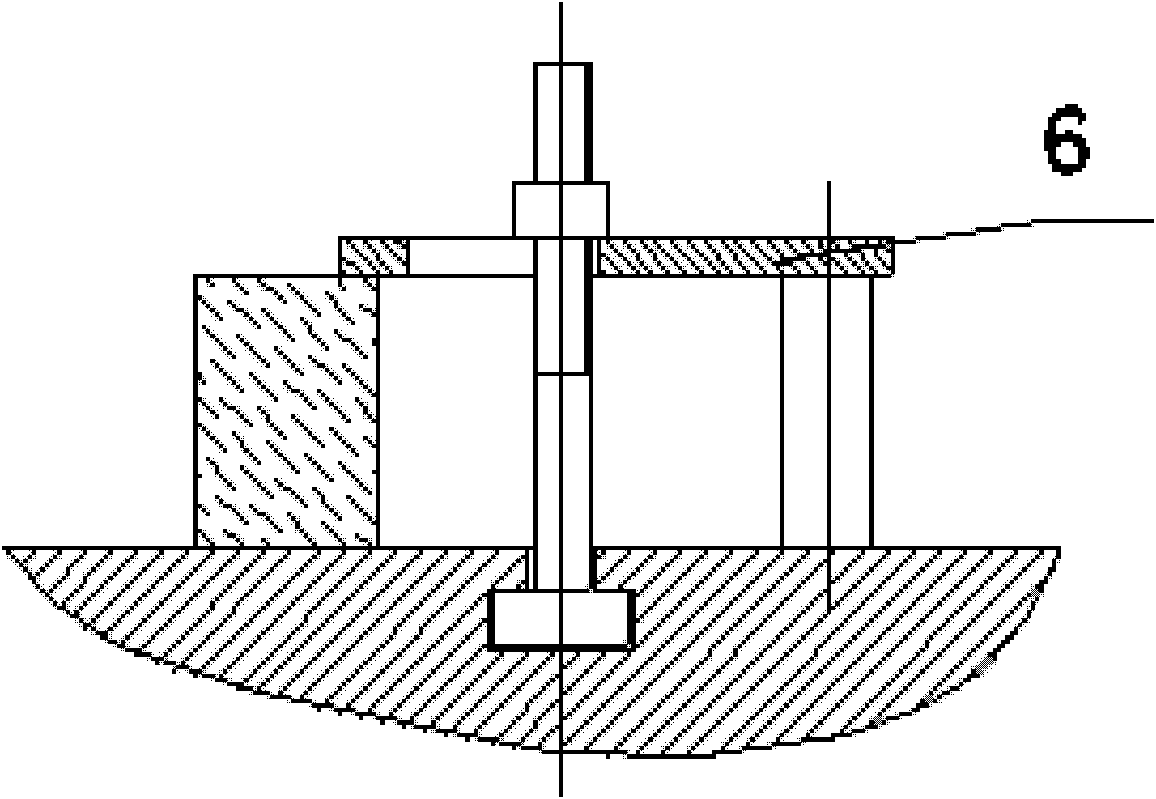
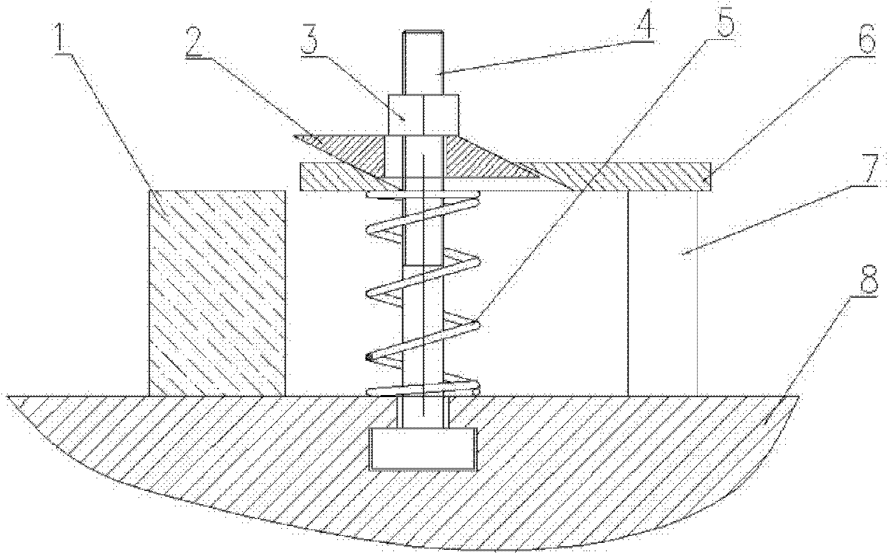
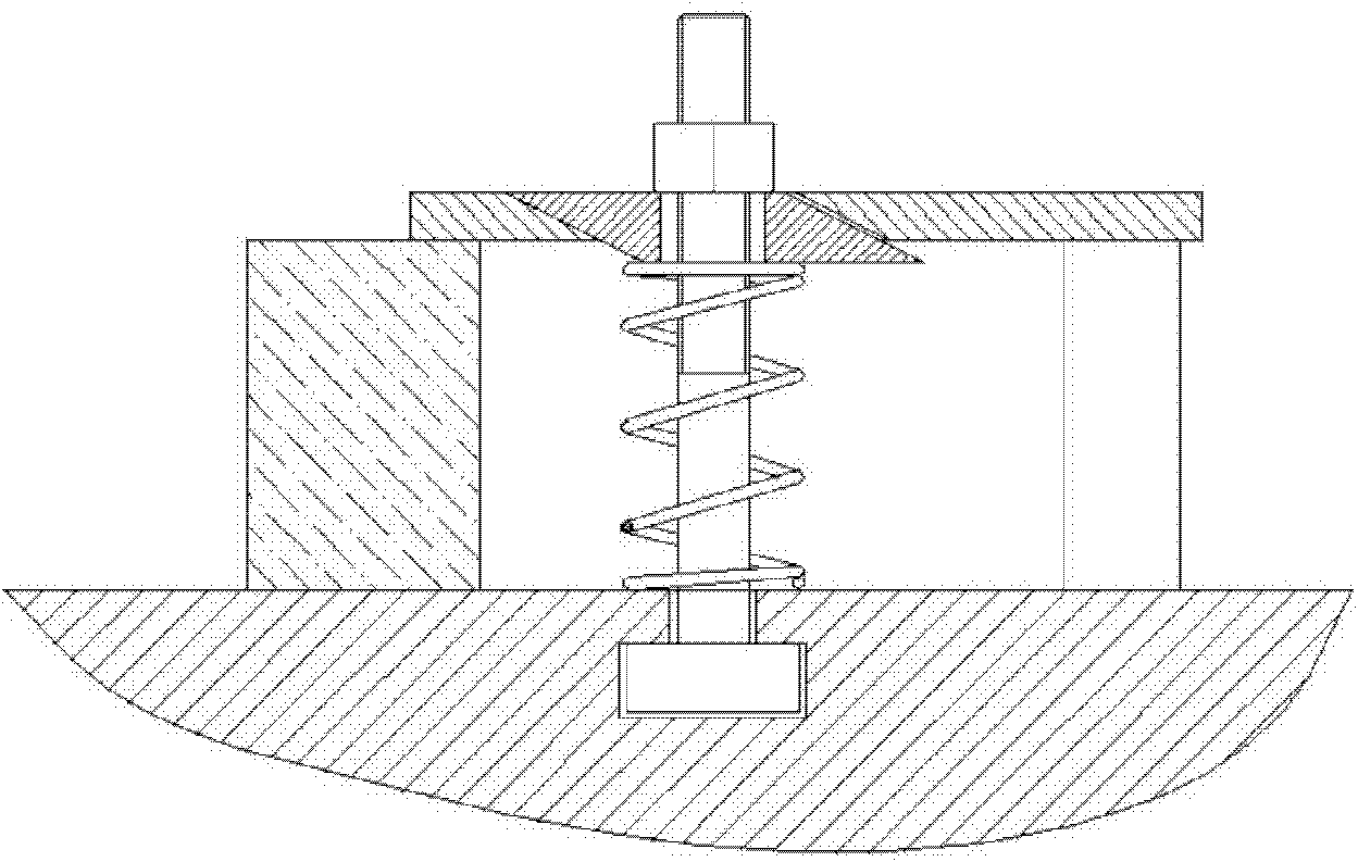
[0011] The pressing plate automatic translation clamping machine of the present invention includes inclined-plane pressing block 2, nut 3, T-shaped bolt 4, spring 5, pressing plate 6, spacer 7, workbench 8, and pressing plate 6 is kept horizontal under the elastic force of spring 5, and the inclined plane The pressing block 2 is in contact with the inclined plane on the left side of the pressing plate 6 under the action of the nut 3 . When the nut 3 is turned, the inclined-plane pressing block 2 moves down under the action of the nut 3, and pushes the pressure plate 6 to move left through the left inclined plane of the inclined-plane pressing block 2. At this time, due to the action of the spring 5, the pressing plate 6 remains horizontal. , until it moves above the workpiece, such as f...


PUM


Abstract

The invention discloses a pressure plate automatic translation clamping machine. A pressure plate remains horizontal under the action of the elasticity of a spring, and an inclined pressure block is contacted with an inclined plane on the left side of the pressure plate under the action of a nut. When the nut is rotated, the inclined pressure block moves downwards under the action of the nut; the pressure plate is pushed to move left through the inclined plane on the left side of the inclined pressure block (because of the action of the spring, the pressure plate still remains horizontal) until the pressure plate moves above a workpiece; and at the moment, the inclined pressure block is pressed above the pressure plate, the nut is continuously screwed, and then the workpiece is pressed tightly. The loosening process is just opposite to the clamping process. When the nut is loosened, the pressure plate pushes the inclined pressure block to move upwards under the action of the spring; and meanwhile, the inclined pressure block drives the pressure plate to move right so as to separate from the workpiece.

Description

technical field [0001] The invention relates to a clamping device, in particular to a positioning clamping device for workpiece machining. Background technique [0002] Such as figure 1 As shown, in the workpiece machining, when the workpiece is placed, the conventional method is to move the pressure plate to the workpiece, and then tighten the compression nut for clamping. This method of positioning is simple and effective, but there is a manual release of the pressure plate. And disadvantages such as inconvenient operation will increase the processing time of a single piece and reduce labor efficiency. Contents of the invention [0003] The purpose of the present invention is to provide a device that can directly position the clamping mechanism for automatic translation of the pressing plate. [0004] In order to achieve the above object, the technical solution of the present invention is: the automatic translation clamping machine of the pressing plate, including incl...

Claims


Application Information

Patent Timeline
Patent Type & Authority Applications(China)
IPC IPC(8): B25B11/00B23Q3/06
Inventor 郭建东刘新宇黄晓光胡怀伟田冀锋寇朝阳
Owner CITIC DICASTAL
Why Eureka
Try Eureka