Heat insulation layer structure

A technology of thermal insulation layer and thermal insulation material, which is applied in the direction of thermal insulation, pipeline protection, pipeline protection through heat insulation, etc. It can solve the problems of thermal insulation material damage, deformation of the protective layer, etc., and achieve the effect of solving the problem of thermal expansion

Active Publication Date: 2011-12-28
CHINERGY CO LTD
View PDF0 Cites 1 Cited by
  • Summary
  • Abstract
  • Description
  • Claims
  • Application Information

AI Technical Summary

Problems solved by technology

[0009] The technical problem to be solved by the present invention is to overcome the defects existing in the existing insulation layer structure, and to avoid deformation of the protective layer and damage to the insulation material caused by the different temperatures on both sides of the insulation layer during the heat preservation process of high-temperature gas

Method used


Image

  • Heat insulation layer structure
  • Heat insulation layer structure
  • Heat insulation layer structure

Examples


Embodiment 1

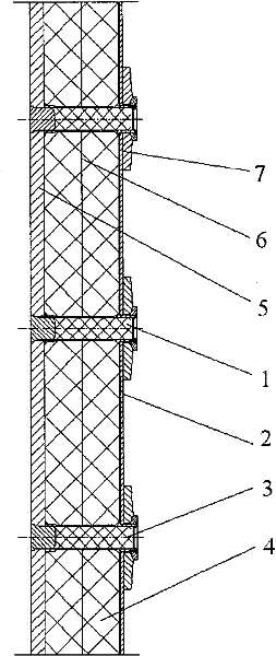
[0034] A longitudinal section view of a vertically placed insulation layer structure (high temperature gas is on the right) as shown in figure 1 shown. When the high temperature gas medium flows vertically, the insulation layer structure must be placed vertically. exist figure 1 In the case shown, the hot gas is on the right, the cover plate 2 is on the right and the fixing plate 5 is on the left. The cover board 5 is fixed on the fixing board 5 through the primary fixing part 1 and the secondary fixing part 3 . The insulating material 4 is filled between the covering plate 2 and the fixing plate 5 , and a convective film 6 is laid at a suitable position in the insulating material 4 . A sealing film 7 is laid next to the cover plate 2 . In this way, a complete insulation layer structure is formed.

Embodiment 2

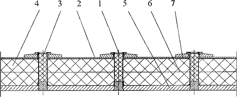
[0036] A longitudinal section view of a horizontally placed insulation layer structure (the upper side is high-temperature gas) such as figure 2 shown. The insulation layer structure of this embodiment is similar to that of Embodiment 1, and the difference from Embodiment 1 is that the insulation layer structure is arranged in a horizontal direction.

Embodiment 3

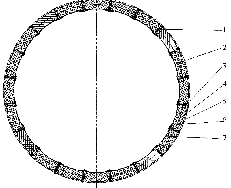
[0038] A longitudinal section view of a cylindrical insulation layer structure (inside and upper side is high-temperature gas) such as image 3 shown. This embodiment is similar to the structure of the thermal insulation layer of the first embodiment, and its difference from the first embodiment is that the structure of the thermal insulation is cylindrical, and at this time, it is required that the fixed parts such as the fixed plate and the cover plate all need to be replaced with belts. A sheet with a certain curvature.


PUM


Abstract

The invention discloses a heat insulation layer structure which comprises a fixing plate (5) and a covering plate (2), wherein the covering plate (2) is fixed and connected with the fixing plate (5) through a primary fixing piece (1) and a secondary fixing piece (3); heat insulation material (4) is paved between the covering plate (2) and the fixing plate (5); a sealing film (7) is arranged on the heat insulation material (4); the primary fixing piece (1) is positioned in the middle of the covering plate (2); and the secondary fixing piece (3) is positioned on the periphery of the covering plate (2). The invention breaks through the limitation of the application field of the common heat insulation structure, can be applied to large-scale heat insulation of gas media of high temperature, high speed and high pressure, and solves the problem of the heat expansion generated on both sides of the heat insulation layer due to different temperatures.

Description

technical field [0001] The invention relates to the technical field of thermal engineering, in particular to a thermal insulation layer structure. Background technique [0002] In the field of thermal systems, a large number of insulation layers are usually laid. Its functions mainly include the following points: [0003] 1) Separate the hot and cold environment in the equipment to reduce heat loss. For example, an insulation layer is often laid on the outer surface of high-temperature equipment and pipelines in order to reduce heat loss. [0004] 2) Separate the cold and hot parts in the equipment to ensure that the ambient temperature of the cold parts is lower than its design temperature limit. For example, the stuffed insulation material in the thermal sleeve of the main steam nozzle of the gas-cooled reactor steam generator. [0005] 3) When the temperature difference on both sides of the same component is large, laying a heat insulation layer can reduce the thermal...

Claims


Application Information

Patent Timeline
Patent Type & Authority Patents(China)
IPC IPC(8): F16L59/04
Inventor 雒晓卫张丽何树延吴莘馨王洪涛李笑天
Owner CHINERGY CO LTD
Why Eureka
Try Eureka