
Method for calibrating infrared probe of shaft temperature detection system by adopting vertical zigzag plate

A shaft temperature detection and infrared probe technology, applied in the field of temperature measurement, can solve the problems of cumbersome operation, long working time, misalignment of optical paths, etc., and achieve the effect of ensuring accuracy and ensuring train safety

Inactive Publication Date: 2010-09-15
BEIJING CTROWELL INFRARED TECHN
View PDF6 Cites 3 Cited by
  • Summary
  • Abstract
  • Description
  • Claims
  • Application Information

AI Technical Summary

Problems solved by technology

[0011] (1) In the static calibration operation, the temperature measurement accuracy detection and the probe installation angle detection are divided into two processes. The angle detection also needs to open the scanning box, which is cumbersome to operate and takes a long time to work
[0012] (2) The optical axis of the laser tube inserted on the probe may not coincide with the actual optical path, and the degree of misalignment is also random, so the error in detecting and adjusting the installation angle of the probe will also be large
[0019] (1) Dynamic detection is difficult to detect and repeat verification at any time when needed, so ground calibration is required as a supplement
[0020] (2) The Z-shaped plate on the experimental vehicle is placed horizontally under the axle box, and what is detected is only the position where the detection point of the probe falls on the Z-shaped plate, and the installation angle of the probe cannot be calculated

Method used


Image

  • Method for calibrating infrared probe of shaft temperature detection system by adopting vertical zigzag plate
  • Method for calibrating infrared probe of shaft temperature detection system by adopting vertical zigzag plate
  • Method for calibrating infrared probe of shaft temperature detection system by adopting vertical zigzag plate

Examples


Embodiment Construction

[0096] The present invention will be further described in detail with reference to the accompanying drawings and embodiments.

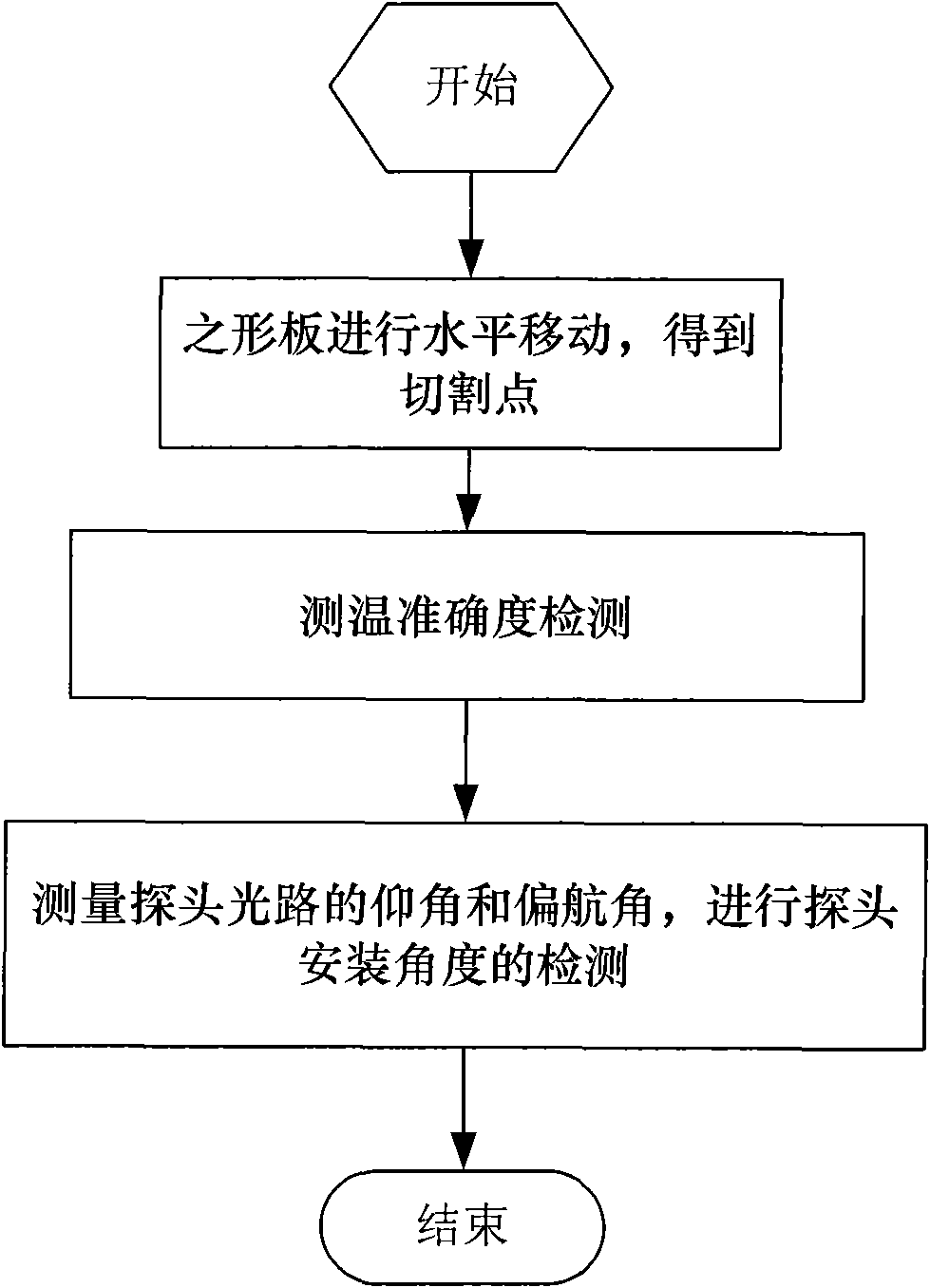
[0097] The present invention is a method for calibrating the infrared probe of the axial temperature detection system by using a vertical shaped plate, the process is as follows figure 1 shown, including the following steps:

[0098] Step 1: The shape plate is moved horizontally to obtain the cutting point;

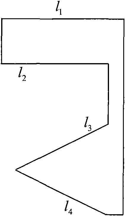
[0099] shape like figure 2 As shown, it is placed vertically between the probe and the black body, and at the same time perpendicular to the horizontal direction and the direction of the rail, and the two sides parallel to the horizontal direction are l 1 and l 2 , the two hypotenuses are l 3 and l 4 ;

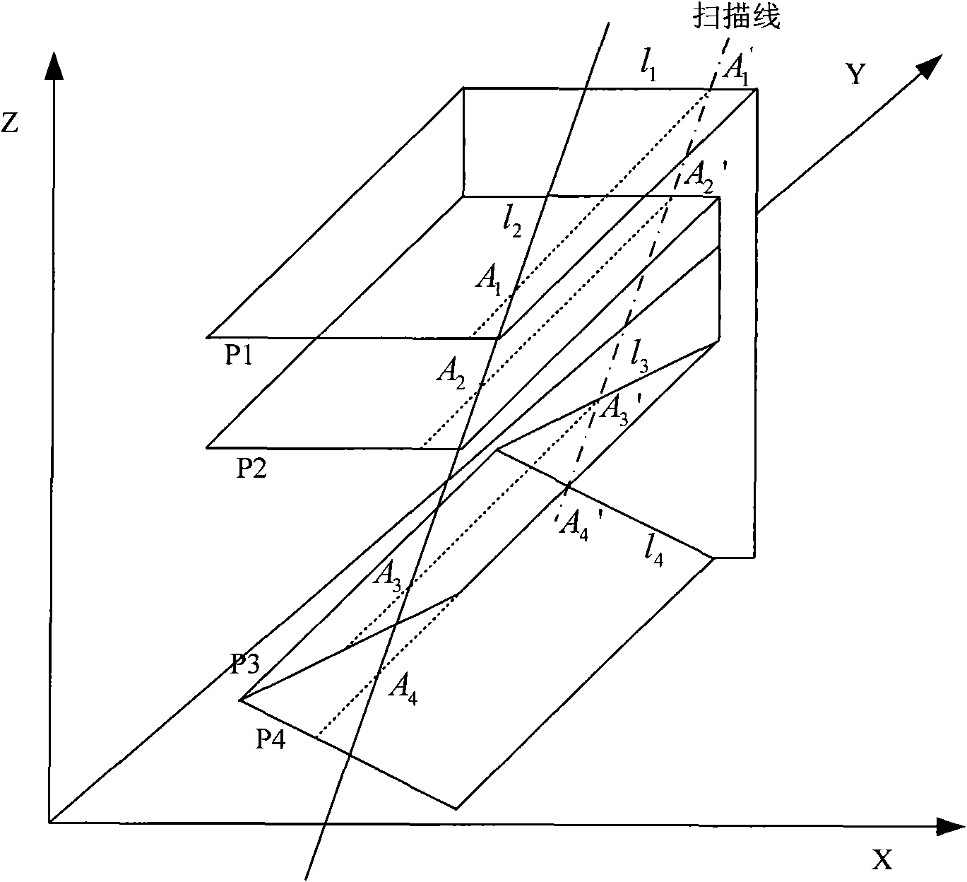
[0100] The Cartesian coordinate system is used, the x-axis is the direction perpendicular to the rails in the horizontal plane, from the inside of the rails to the outside of the rails, the y-axis is the direction parallel to the rails in ...


PUM


Abstract

The invention discloses a method for calibrating an infrared probe of a shaft temperature detection system by adopting a vertical zigzag plate, which can be used for simultaneously calibrating the installation angle and the temperature measurement accuracy degree of the double-probe infrared probe of the infrared shaft temperature detection system. The method comprises the following steps of: 1. horizontally moving the zigzag plate to obtain a cutting point; 2. detecting the temperature measurement accuracy degree; and 3. measuring an elevation angle and a yaw angle of an optical path of the probe and detecting the installation angle of the probe. The invention has the characteristics of easy operation, simple flow and short operation time, can be used for simultaneously detecting the installation angle and the temperature measurement precision of two probes of a double-probe device and provides specific parameters of the installation angle of the probe that needs to be regulated according to the detection result.

Description

technical field [0001] The invention relates to a method for calibrating an infrared probe of an axial temperature detection system by using a vertical shaped plate, which belongs to the technical field of temperature measurement. Background technique [0002] Infrared shaft temperature detection system (abbreviated as THDS) has been widely used and developed in the safety guarantee of railway transportation. At present, more than 5,000 sets of THDS equipment have been installed on 80,000 kilometers of railway lines across the country, and they are eager to cut shafts for anti-blocking. The accident made an outstanding contribution. [0003] In the application of THDS equipment, the online inspection and calibration of the probe is an important operation procedure to ensure the correct measurement and prediction of the thermal axis of the infrared shaft temperature detection system, and it is also essential to ensure the normal operation of the infrared shaft temperature det...

Claims


Application Information

Patent Timeline
IPC IPC(8): G01J5/02B61K9/04
Inventor 姜云绯关亮朱波
Owner BEIJING CTROWELL INFRARED TECHN
Learn More