Locked tracking method of helicopter in the inspection process of electric power circuits
A technology for power lines and helicopters, used in overhead lines/cable equipment, reflection/re-radiation of radio waves, satellite radio beacon positioning systems, etc., can solve the problems of low accuracy, affecting acquisition, and high inspection costs, Achieve good analysis and detected targets, eliminate inaccurate positioning errors, and improve the efficiency of inspections
- Summary
- Abstract
- Description
- Claims
- Application Information
AI Technical Summary
Problems solved by technology
Method used
Image


Examples
Embodiment Construction
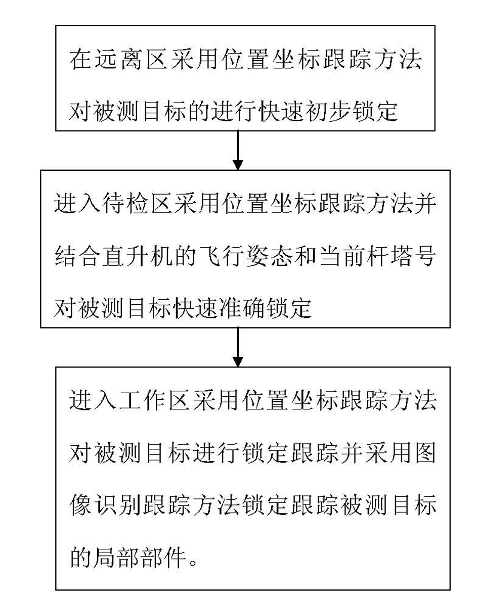
[0043] Such as figure 1 Shown, the locking tracking method of helicopter inspection power line, comprises the following steps:
[0044] (1) Use the position coordinate tracking method in the remote area to determine the three-dimensional rotation angle of the pod according to the current position coordinates of the helicopter and the position coordinates of the measured target, and quickly and initially lock the measured target;
[0045] (2) When entering the area to be inspected, the position coordinate tracking method is used. According to the current position coordinates of the helicopter and the position coordinates of the target to be measured, the flight attitude of the helicopter is determined through the flight attitude detector and the current tower number is read by a radio frequency card reader to determine Control the three-dimensional rotation angle of the pod to quickly and accurately lock the measured target;
[0046] (3) When entering the working area, the pos...
PUM
 Abstract
Description
Claims
Application Information
 - Generate Ideas
- Intellectual Property
- Life Sciences
- Materials
- Tech Scout
- Unparalleled Data Quality
- Higher Quality Content
- 60% Fewer Hallucinations
Browse by: Latest US Patents, China's latest patents, Technical Efficacy Thesaurus, Application Domain, Technology Topic, Popular Technical Reports.
© 2025 PatSnap. All rights reserved.Legal|Privacy policy|Modern Slavery Act Transparency Statement|Sitemap|About US| Contact US: help@patsnap.com