

Coil electric conductor device and manufacture method thereof
A coil conductor and manufacturing method technology, applied in coil manufacturing, coils, electrical components, etc., can solve the problems of large overall height, troublesome use of devices, short circuit of coil conductors, etc., to increase the connection area, improve connection reliability, reduce The effect of the possibility of a short circuit
- Summary
- Abstract
- Description
- Claims
- Application Information
AI Technical Summary
Problems solved by technology
Method used
Image

Examples
Embodiment Construction
[0031] The present invention will be further described below in conjunction with the accompanying drawings and preferred embodiments.
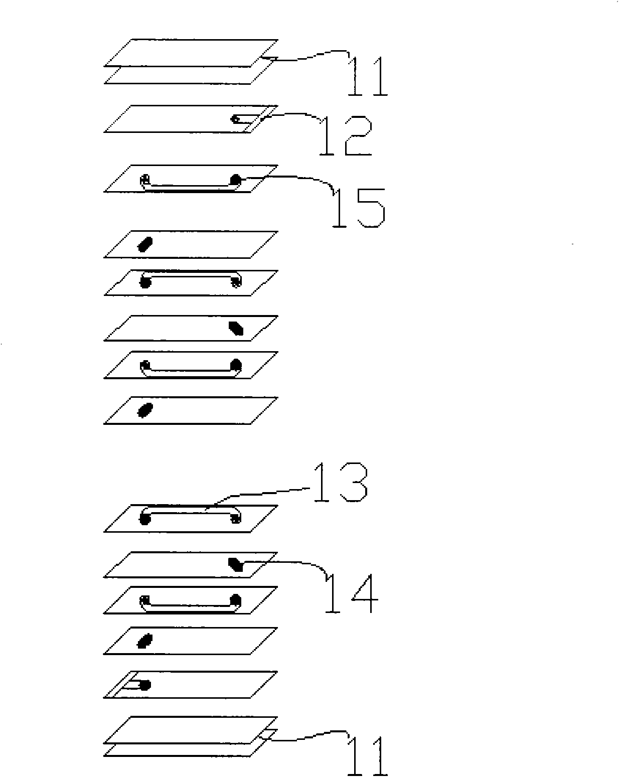
[0032] An embodiment of a coil electrical conductor device of the present invention is figure 1 , figure 2 with image 3 shown.
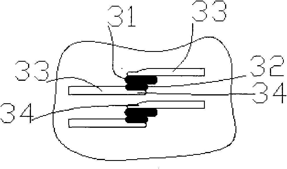
[0033] Such as figure 1 As shown, the coil conductor 12, the lead-out end 13, the connection point 14, the connection point 15, and the cast slurry layer 11 are laminated to form a helical coil device. Such as Figure 8 As shown, a small cavity 82 is formed at the end of the coil conductor 81 , and the connection point 15 is printed on the end portion 82 .
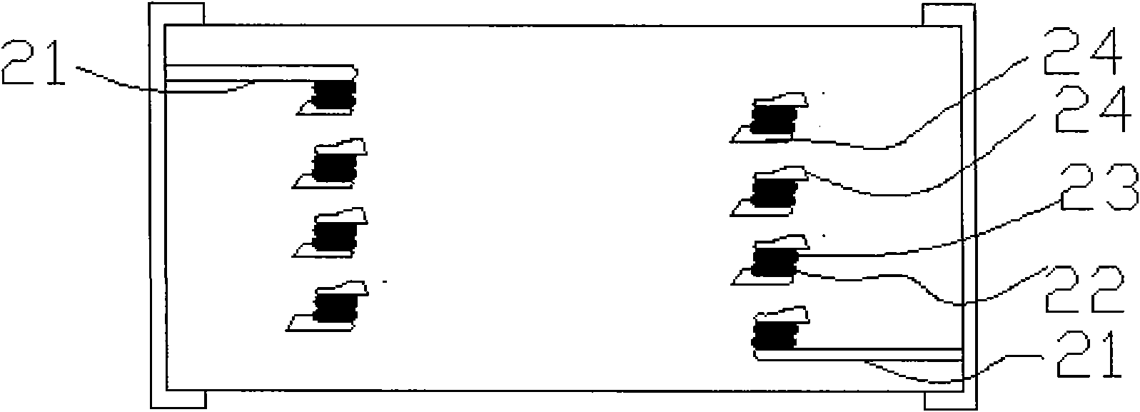
[0034] Such as Figure 9 Shown is a top view from the top of this embodiment. Among them, the state obtained by overlapping the ceramic layer 94 , the lead-out end 92 , the connection point 93 and the coil conductor 91 . and Figure 4 Compared to the sectional view showing the center of the coil electrical conductor device, external electrodes are for...
PUM
 Abstract
Description
Claims
Application Information