Power module insulation method and power module assembly

A technology for power modules and components, applied in electrical components, electric solid devices, semiconductor devices, etc., can solve the problem of impracticality, no good solution, and difficulty in injecting three-proof glue into PCB and power module three-proof glue, etc. question

Active Publication Date: 2014-10-15
SCHNEIDER ELECTRIC IND SAS
View PDF1 Cites 0 Cited by
  • Summary
  • Abstract
  • Description
  • Claims
  • Application Information

AI Technical Summary

Problems solved by technology

But precisely because the conformal glue is usually liquid, after the power module is installed on the PCB, it is difficult to inject the conformal glue between the PCB and the power module so that the conformal glue is evenly distributed between each pin
To put it simply, some pins have three-proof glue between them, while some pins have no three-proof glue between them. Therefore, this solution is not practical for the insulation of the space between the PCB and the power module.
[0006] At present, there is no good solution for the limitation of electrical clearance caused by the application of similar modules in the occasion of overvoltage class III

Method used


Image

  • Power module insulation method and power module assembly
  • Power module insulation method and power module assembly
  • Power module insulation method and power module assembly

Examples


Embodiment Construction

[0023] Preferred embodiments of the present invention will be described in detail below with reference to the accompanying drawings. It should be understood that the specific embodiments shown and described herein are for illustration only, and are not intended to limit the present invention.

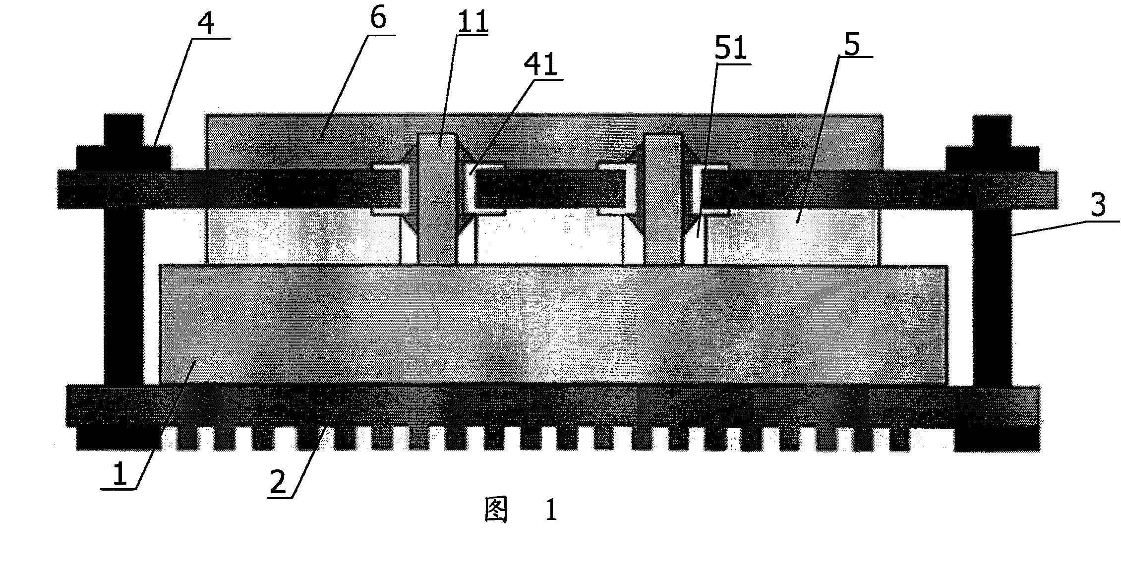
[0024] like figure 1 As shown, usually the power module 1 and the heat sink 2 are installed together, and then the pins 11 of the power module 1 are inserted into the corresponding pads 41 on the printed circuit board 4 . And the heat sink 2 and the printed circuit board 4 are connected together by bolts 3 , so that the power module 1 and the printed circuit board 4 are installed together. Then, the printed circuit board 4 is turned over, and each pin 11 protruding from the pad 41 is soldered, so as to complete the mechanical and electrical connection between the power module 1 and the printed circuit board 4 .

[0025] However, as mentioned in the background art, as the size of the p...


PUM


Abstract

The invention discloses a power module insulating method and a power module assembly. The method comprises the following steps: arranging an insulated material layer on one side of a pin on the power module and arranging the power module on a printed circuit board so as to place the insulated material layer between the printed circuit board and the power module, wherein the space between the printed circuit board and the power module is filled with the insulated materials. Through the method, the insulation restriction between the pins of the power module is eliminated so the electric equipment using the power module can meet the insulation demand of pollution level 3 and overvoltage level III.

Description

technical field [0001] The present invention generally relates to a method of power module isolation and a power module assembly for use in the method. The power module, such as an IGBT module, is usually used in power electronic application products such as frequency converters and power supplies. Background technique [0002] In recent years, products have become more and more miniaturized. With the trend of product miniaturization, the size of the power module has become smaller and smaller, so that the distance between the pins of the power module has been shortened. The direct problem is that the creepage distance and electrical clearance between the pins of the power module are shortened, so that the power module cannot meet the pollution degree 3 (DP3) and overvoltage level III (OVC III) specified in the product standard. application occasions. Wherein the creepage distance (creeping distance) refers to the shortest space distance measured along the insulating surfa...

Claims


Application Information

Patent Timeline
Patent Type & Authority Patents(China)
IPC IPC(8): H01L21/48H01L21/58H01L21/60H01L23/29
Inventor 菲利普·柏德松李欣王静
Owner SCHNEIDER ELECTRIC IND SAS
Why Eureka
Try Eureka