
Digital television receiving equipment and video data decoding method thereof

A technology for digital TV receiving and receiving equipment, which is applied in the field of digital TV receiving equipment and its video data decoding, and can solve problems such as software data decoding methods that have not yet been seen

Inactive Publication Date: 2010-09-15
高平
View PDF0 Cites 6 Cited by
  • Summary
  • Abstract
  • Description
  • Claims
  • Application Information

AI Technical Summary

Problems solved by technology

With the continuous improvement of the processing capacity and speed of digital signal processors, it is entirely possible to use programmable digital signal processors to realize the entire high-definition digital TV source decoder, but there is no relevant effective and convenient software data decoding. method

Method used


Image

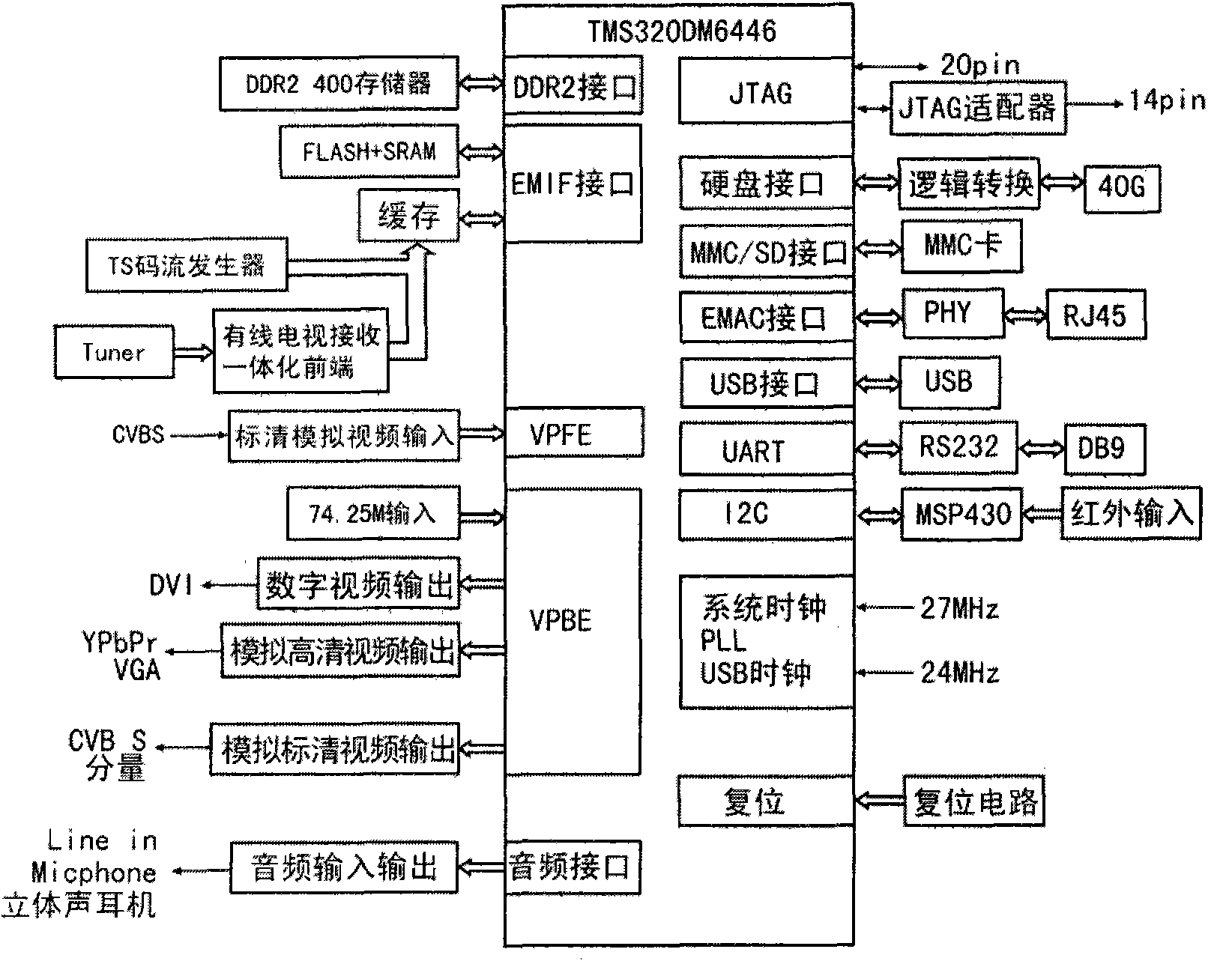
  • Digital television receiving equipment and video data decoding method thereof
  • Digital television receiving equipment and video data decoding method thereof
  • Digital television receiving equipment and video data decoding method thereof

Examples


Embodiment Construction

[0017] Below in conjunction with the present invention is described further:

[0018] The hardware that realizes the present invention comprises: cable television reception integrated front-end circuit board, FIFO cache circuit board, central processing unit circuit board and external expansion memory, its central processing unit circuit board comprises DM6446 chip, DDR2 memory, NORFLASH, video coder, Audio CODEC and infrared control unit, external expansion memory includes hard disk, MMC card, U disk.

[0019] The connection method between the above-mentioned components is: the cable TV high-frequency signal is added to the integrated front end of the cable TV receiver, then connected to the FIFO buffer circuit board, then connected to the EMIF interface socket of the central processor circuit board, and finally the 3Q9 socket of the central processor circuit board The plug is connected to the YPbPr interface of the TV, and the hard disk, MMC card and U disk are respectively ...


PUM


Abstract

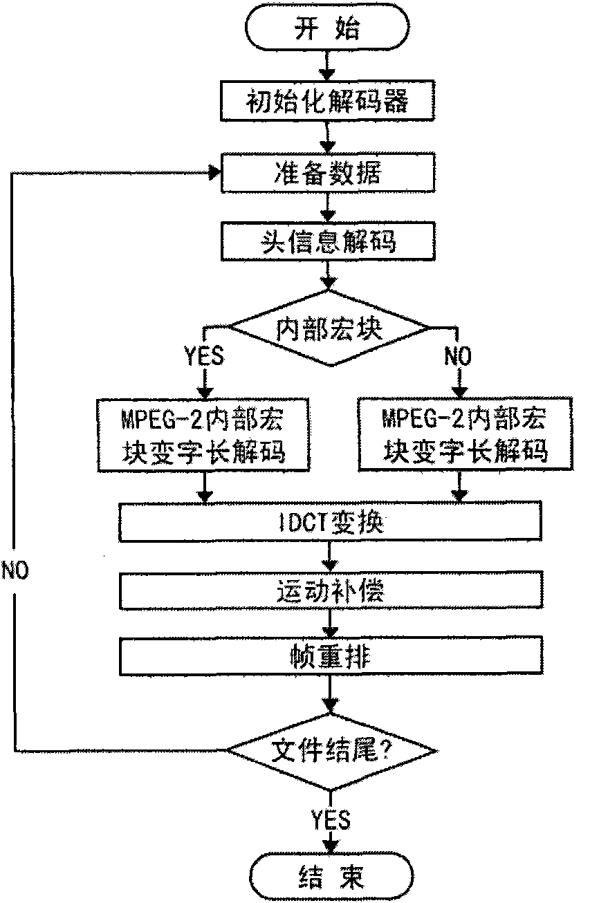
The invention discloses digital television receiving equipment and a video data decoding method thereof. The hardware and the connection mode are that: a television high-frequency signal is applied to a television receiving front end, connected with an FIFO cache circuit board, and connected with an EMIF interface on a central processor; and finally, a 3Q9 plug on the central processor is connected with a YPbPr interface of the television, and a hard disk, an MMC card and a U disk are connected with a corresponding interface respectively. The data decoding method comprises the following steps of: (1) inputting a DVB-C wired television radio-frequency signal; (2) transferring a code stream to an inter-chip L2 upper buffer area by using EDMA for head information decoding; (3) if the head information is an inner macro block, calling IMG-mpeg2-vld-intra for decoding, and outputting the decoded IDCT coefficient; (4) if the head information is a non-inner macro block, calling MG-mpeg2-vld-inter for decoding, and outputting the decoded IDCT coefficient; (5) calling a library function IMG-idct-8x8-12q4 for IDCT, and performing motion compensation and frame rearrangement so as to acquire the decoded data; and (6) computing 1 / 2 pixel precision motion compensation in a motion compensation module by using an iMX processor in VICP.

Description

technical field [0001] The invention relates to a digital TV receiving device and a video data decoding method thereof. Background technique [0002] With the development of the radio and television industry, digital television has gradually entered people's lives. The most common implementation of digital high-definition television (HDTV) source decoders is based on dedicated chips, such as the early STMicroelectronics three-chipset (ST20, STi7000, and STi4600), and today's dedicated chip SoC (STi7100, BCM3563) Wait. The advantage of these schemes is that the special-purpose chip has strong functions, the technology is relatively mature, and the product development cycle is short. The disadvantage is that most of the special-purpose chips are aimed at specific functional requirements and standards, and use special-purpose hardware to realize source decoding, which lacks high flexibility and wide adaptability. Since the advent of Digital Signal Processor (DSP—Digital Sign...

Claims


Application Information

Patent Timeline
IPC IPC(8): H04N5/44H04N5/14H04N7/10
Inventor 高平
Owner 高平
Learn More