Remote management system for LED street lamp

A remote management system and technology for LED street lamps, applied in the field of remote management systems for LED street lamps, can solve the problems of traditional energy consumption, depletion, serious environmental pollution, etc.

Active Publication Date: 2010-09-15
湖南终南山科技发展有限公司
View PDF10 Cites 35 Cited by
  • Summary
  • Abstract
  • Description
  • Claims
  • Application Information

AI Technical Summary

Problems solved by technology

[0003] In addition, the industrialization of human beings has not only caused increasingly serious environmental pollution, but also consumed a large amount of energy

Method used


Image

  • Remote management system for LED street lamp
  • Remote management system for LED street lamp
  • Remote management system for LED street lamp

Examples


Embodiment 1

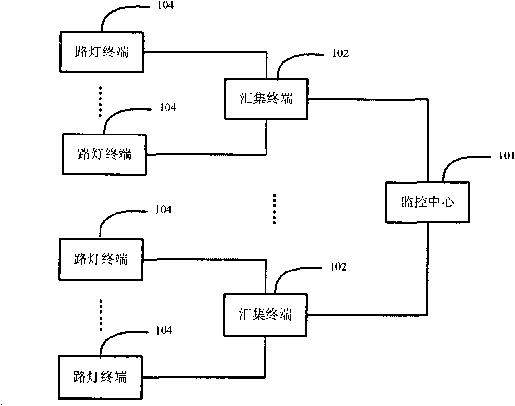
[0038] figure 1 It is a structural schematic diagram of the LED street lamp remote management system of the present invention. see figure 1 In this embodiment, the LED street lamp remote management system includes a monitoring center 101, a collection terminal 102, and a street lamp terminal 104. One collection terminal 102 is installed on one LED street lamp of each group of street lamps, and one collection terminal 102 is installed on each LED street lamp of the remaining groups. street lamp terminal 104 . In the street lamp group, each street lamp terminal 104 is connected to the collection terminal 102 of the group through a short-distance wireless network, such as ZigBee and Wi-Fi, and the collection terminal 102 of each group is connected through a wired network, a wireless network, or a combination of wired and wireless. The network is connected to the monitoring center 101, such as DDN private network, Internet and 3G, GPRS, CDMA mobile network, etc. According to the...

Embodiment 2

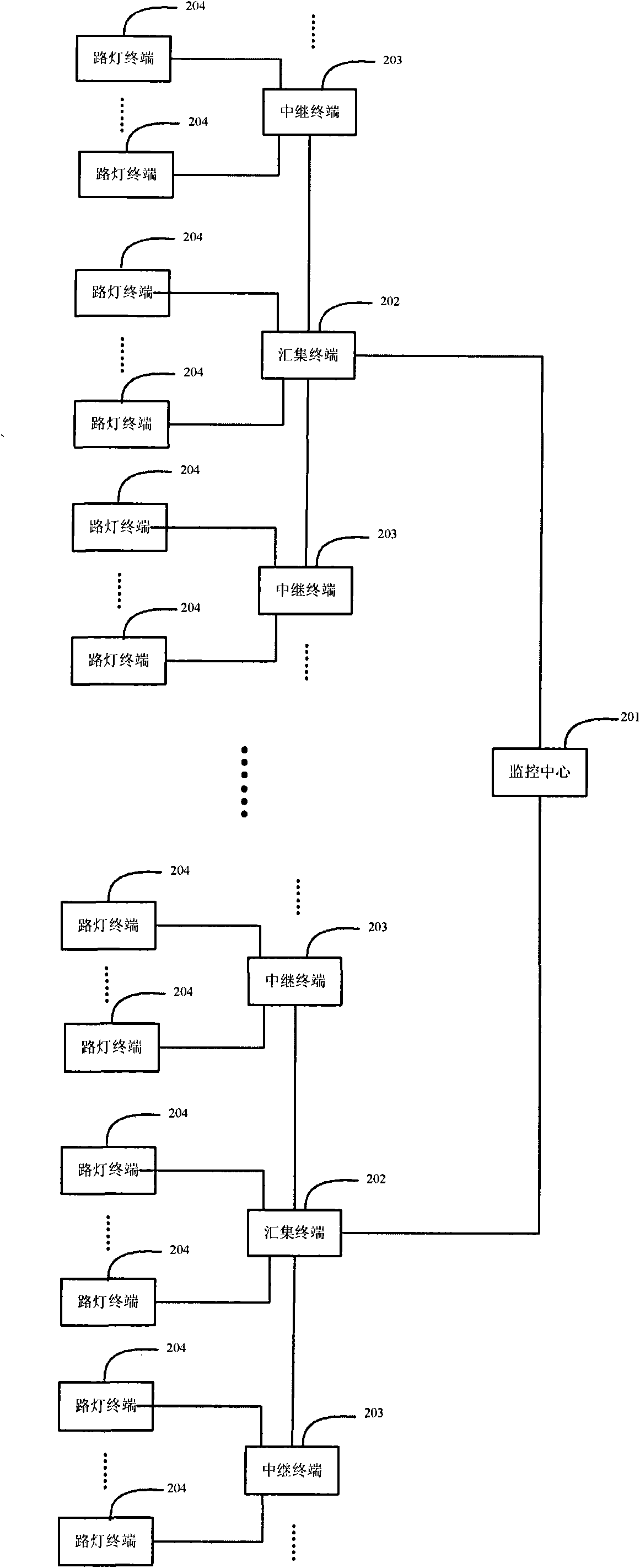
[0045] figure 2 It is another structural schematic diagram of the LED street lamp remote management system of the present invention. see figure 2 , the LED street lamp remote management system in this embodiment includes a monitoring center 201, a collection terminal 202, a relay terminal 203, and a street lamp terminal 204. A collection terminal 202 is installed on an LED street lamp of each group of street lamps, and the interval between the street lamps in this group is Several pole LED street lamps are selected, on which relay terminals 203 are installed, and street lamp terminals 204 are installed on the remaining pole LED street lamps of this group of street lamps. In a street lamp group, each street lamp terminal 204 is connected to the only collection terminal 202 or relay terminal 203 of the group through a short-distance wireless network, and the selection of the only collection terminal 202 or relay terminal 203 is usually based on the proximity in the sense of g...


PUM


Abstract

The invention provides a remote management system of an LED street lamp, comprising a street lamp terminal, a collection terminal and a monitoring center, wherein the street lamp terminal is used for acquiring the operation state information of the located LED street lamp and controlling the located LED street lamp according to a control command of the monitoring center; the collection terminal is used for acquiring the operation state information of the located LED street lamp, transmitting the operation state information of the located LED street lamp and the operation state information acquired by the street lamp terminals of a street lamp group to the monitoring center, controlling the located LED street lamp according to the control command of the monitoring center and transmitting the control command of the monitoring center to the other street lamp terminals of the street lamp group; and the monitoring center is used for controlling the LED street lamps according to user needs or the operation state information of the LED street lamps. The invention can be used for effectively carrying out real-time remote management on the LED street lamps, ensures the reliable operation of the LED street lamps, enhances the operation quality of the LED street lamps and also improves the management efficiency of the LED street lamps.

Description

technical field [0001] The invention belongs to the technical field of electric power control, in particular to a remote management system for LED street lamps. Background technique [0002] With the development of the times, the pace of modernization is accelerating, people's living standards are constantly improving, and the demand for road lighting and lighting projects is also greater. However, in the existing technology of LED street lamps, people still adopt the method of on-site maintenance and management, and the operators regularly maintain and overhaul the LED street lamps, resulting in low management efficiency, unable to understand the operating status of LED street lamps in real time, and find abnormal faults in time Condition. Conventional remote controllers can only operate a single lamp, which is also inefficient and difficult to meet the requirements. Therefore, it is imminent to develop a remote management system that can uniformly manage LED street light...

Claims


Application Information

Patent Timeline
IPC IPC(8): H05B37/02
CPCY02B20/72
Inventor 李珂卞松江邓绍根范劲钟
Owner 湖南终南山科技发展有限公司
Why Eureka
Try Eureka