Optical network parameter testing and diagnosing device and method

A technology for optical fiber network and parameter testing, which is applied in transmission monitoring/testing/fault measurement systems, electromagnetic wave transmission systems, electrical components, etc. Control problems such as multi-instrument testing to achieve the effect of reducing workload and realizing remote management

Active Publication Date: 2016-03-23
THE 41ST INST OF CHINA ELECTRONICS TECH GRP
View PDF4 Cites 10 Cited by
  • Summary
  • Abstract
  • Description
  • Claims
  • Application Information

AI Technical Summary

Problems solved by technology

In the test system invented here, the bit error rate test of optical fiber transmission, the location of fiber fault breakpoints, and the test of optical return loss cannot be realized; moreover, it is impossible to realize simultaneous control of multi-i

Method used


Image

  • Optical network parameter testing and diagnosing device and method
  • Optical network parameter testing and diagnosing device and method
  • Optical network parameter testing and diagnosing device and method

Examples


Example Embodiment

[0038] The present invention will be described in detail below in conjunction with the drawings:

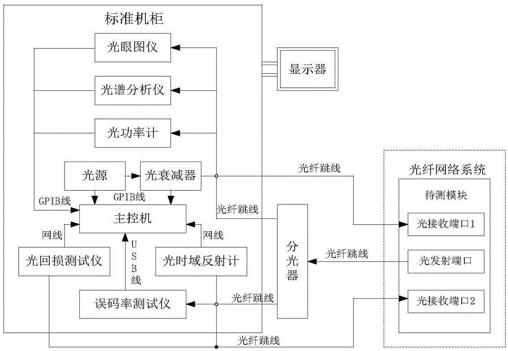
[0039] An optical fiber network parameter test and diagnosis device, such as figure 1 Shown, including: the main control machine and the optical fiber network test instrument, light source and optical attenuator respectively connected with the main control machine; optical fiber network test instrument including optical eye diagram, spectrum analyzer, optical power meter, bit error rate tester , Optical time domain reflectometer and optical return loss tester; optical power meter, optical attenuator, spectrum analyzer, light source and optical eye diagram are connected to the main control machine using GPIB cable, and the bit error rate tester is connected to the main control machine using USB cable The optical time domain reflectometer and the optical return loss tester are connected to the main control machine using a network cable.

[0040] The optical transmitting port of the modu...


PUM


Abstract

The invention discloses an optical network parameter testing and diagnosing device and method. The optical network parameter testing and diagnosing device comprises an optical network testing instrument which includes an optical eye diagram meter, an spectrum analyzer, an optical power meter, an error rate tester, an optical time domain reflectometer and an optical return loss tester; an optical source is connected with an optical attenuator through an optical fiber jumper; the optical attenuator is connected with an optical receiving end of a tested module through the optical fiber jumper; the tested module is connected with an optical splitter through the optical fiber jumper; the optical splitter after splitting lights is respectively connected with the optical eye diagram meter, the spectrum analyzer, the optical power meter and the error rate tester; and the optical time domain reflectometer and the optical return loss tester are respectively connected with the tested module. The optical network parameter testing and diagnosing device and method have the beneficial effects that multiple optical network parameter testing instruments are integrated, frame formation of the testing instruments is realized, and multiple testing instruments can be configured flexibly for a cooperative test under unified management of an upper computer.

Description

technical field [0001] The invention relates to the technical field of optical fiber network parameter testing, in particular to an optical fiber network parameter testing and diagnosis device and method. Background technique [0002] With the large-scale construction and maintenance of optical fiber networks and the rapid development of optical fiber communication systems, it is essential to test various optical fiber network parameters. In an optical fiber network system, there are often multiple parameters that need to be tested, and the test of an optical fiber network parameter sometimes requires the use of multiple test instruments at the same time, which often requires the use of various test instruments to build different test platforms ; Moreover, in order to improve the test efficiency in an optical fiber network system, it is often necessary to use different test instruments to test multiple parameters at the same time; it is also necessary to conduct unified anal...

Claims


Application Information

Patent Timeline
IPC IPC(8): H04B10/07H04B10/071
CPCH04B10/07H04B10/071
Inventor 徐桂城张志辉
Owner THE 41ST INST OF CHINA ELECTRONICS TECH GRP
Why Eureka
Try Eureka