Wireless distributed monitoring method, equipment and system

A technology of distributed monitoring and monitoring equipment, applied in transmission systems, signal transmission systems, information technology support systems, etc., can solve the problem that remote automatic control cannot be realized, the control system design is complicated, and the PLC programmable controller loop control drive capability is small. And other issues

Pending Publication Date: 2017-12-15
WUHAN WEIZHICHUANGDA TECH CO LTD
View PDF12 Cites 12 Cited by
  • Summary
  • Abstract
  • Description
  • Claims
  • Application Information

AI Technical Summary

Problems solved by technology

[0002] In the field of road lighting and industrial control, there are a large number of AC power supply and distribution facilities. These AC power supply and distribution facilities distribute the input AC power to the power supply circuit and supply power to the loads of each circuit. Each circuit is controlled manually or by a timer. The loop switch controls the power supply. This type of control method requires manual control or manual regular adjustment of the time control, and cannot achieve flexible remote automatic control.
[0003] At present, although some manufacturers use PLC programmable controllers for automatic switch control of power supply and distribution circuits in order to realize automatic control, the PLC programmable controllers have relatively small control drive capabilities, and external intermediate relays are required to achieve high-power circuit power supply. The control drive of the contactor, and the programmable controller only provides Ethernet interface and RS232, RS485 communication interface, it needs external wireless communication GPRS communication interruption to realize remote automatic control, and the programmable controller needs an additional external power supply module for its Therefore, the use of programmable controllers to realize automatic control of power supply and distribution circuits requires pe

Method used


Image

  • Wireless distributed monitoring method, equipment and system
  • Wireless distributed monitoring method, equipment and system
  • Wireless distributed monitoring method, equipment and system

Examples


Embodiment Construction

[0067] Below in conjunction with specific embodiment the present invention is described in further detail:

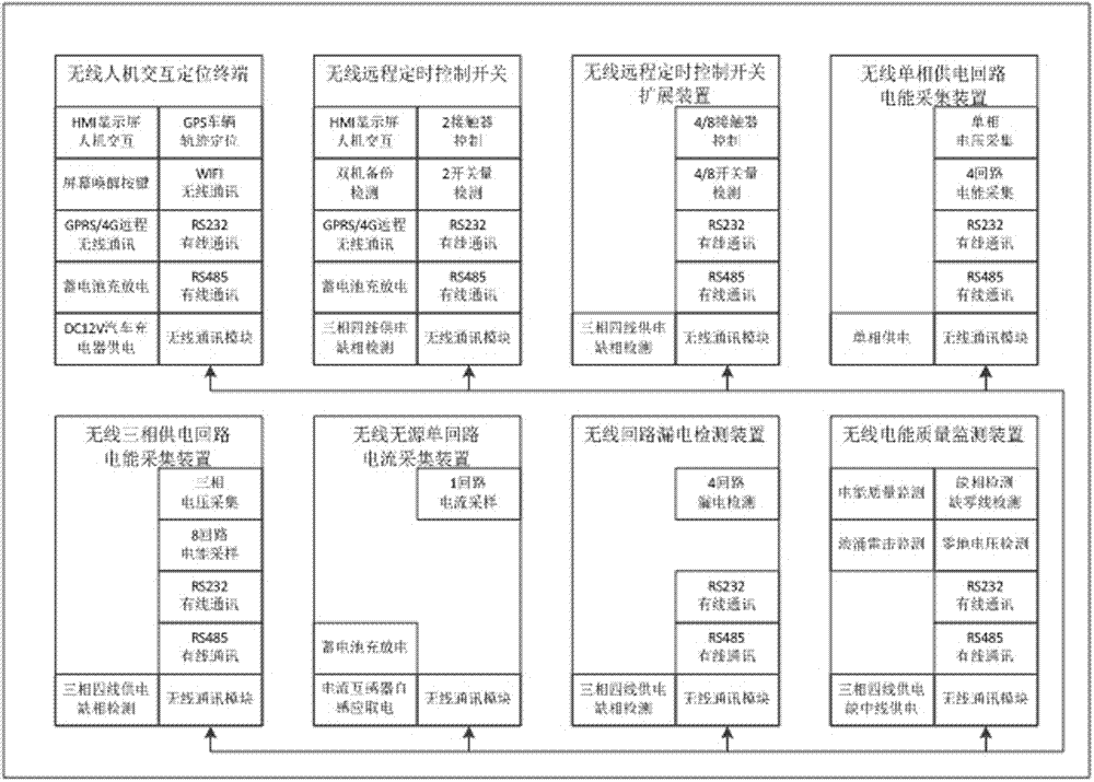
[0068] The structure schematic diagram of the wireless distributed monitoring equipment of the present invention is as figure 1 shown. The monitoring equipment includes a wireless human-computer interaction positioning terminal module, a wireless remote timing control switch module, a wireless remote timing control switch expansion device module, a wireless single-phase power supply circuit power collection device module, a wireless three-phase power supply circuit power collection device module, a wireless wireless The source single-loop current acquisition device module, the wireless loop leakage detection device module, and the wireless power quality monitoring device module all include a wireless communication unit in the above-mentioned 8 modules, and the wireless communication between 8 different types of modules is realized through the wireless communication unit...


PUM


Abstract

A wireless distributed monitoring method, equipment and system is designed for AC power supply and distribution facilities. According to the invention, the method, equipment and system are mainly designed through the wiring-free advantage of wireless communication according to a distributed module group design method, achieve the remote intelligent wireless management, control and measurement of the AC power supply and distribution facilities, achieve the switching power supply of each power supply loop in the AC power supply and distribution facilities, the management and measurement of the voltage, current, power and electric energy, the early warning and alarm of all electric quantity parameters, the monitoring of the working states of all power distribution devices, the monitoring of the electric energy quality, the power supply harmonic components and the surge lightning stroke of the power supply loops, and can guarantee the reliable and safe power supply and operation of various types of AC power supply and distribution facilities.

Description

technical field [0001] The invention relates to the fields of the Internet of Things, road lighting and industrial control, and specifically relates to a wireless distributed monitoring method, device and system. Background technique [0002] In the field of road lighting and industrial control, there are a large number of AC power supply and distribution facilities. These AC power supply and distribution facilities distribute the input AC power to the power supply circuit, and supply power to each circuit load. Each circuit is controlled manually or by a timer. The loop switch controls the power supply. This kind of control method requires manual control or manual regular adjustment of time control, and cannot realize flexible remote automatic control. [0003] At present, although some manufacturers use PLC programmable controllers for automatic switch control of power supply and distribution circuits in order to realize automatic control, the PLC programmable controllers ...

Claims


Application Information

Patent Timeline
IPC IPC(8): H02J13/00H04L29/08G08C17/02
CPCH02J13/0062H02J13/0075H04L67/025H04L67/12G08C17/02Y04S40/126Y02E60/00
Inventor 刘芳齐芸芸
Owner WUHAN WEIZHICHUANGDA TECH CO LTD
Why Eureka
Try Eureka