Ultrasonic flaw detection method and device thereof

一种探伤装置、超声波的技术,应用在测量装置、使用声波/超声波/次声波分析固体、使用声波/超声波/次声波进行材料分析等方向,能够解决难以检测缺陷回波等问题

Active Publication Date: 2010-09-15
NIPPON KURAUTO KUREEMAA FUERUSUTAA
View PDF2 Cites 13 Cited by
  • Summary
  • Abstract
  • Description
  • Claims
  • Application Information

AI Technical Summary

Problems solved by technology

[0055] However, in reality, due to the reflection echo (surface echo) generated in the above-mentioned incidence interval, the area near the incidence interval inside the test material becomes a dead zone (insensitive zone) where it is difficult to detect defect echoes.
[0056] Furthermore, although it is very small compared with the dead zone in the above-mentioned incident side, due to the reflected echo (bottom echo) generated in the above-mentioned opposing zone opposite to the incident zone, there will be There is also a slight dead zone near the opposite edge
In addition, even if such a dead zone is neglected, as described above, in a cross-sectional view, it is possible to perform flaw detection together by one array probe in which a plurality of vibrators are arranged in an arc shape. The fan-shaped part of the interval is restricted, and the undetected area remains relatively wide in the tested material

Method used


Image

  • Ultrasonic flaw detection method and device thereof
  • Ultrasonic flaw detection method and device thereof
  • Ultrasonic flaw detection method and device thereof

Examples


Embodiment Construction

[0114] Embodiments of the present invention will be described below with reference to the drawings.

[0115] Figure 1 to Figure 18 One embodiment of the present invention is shown.

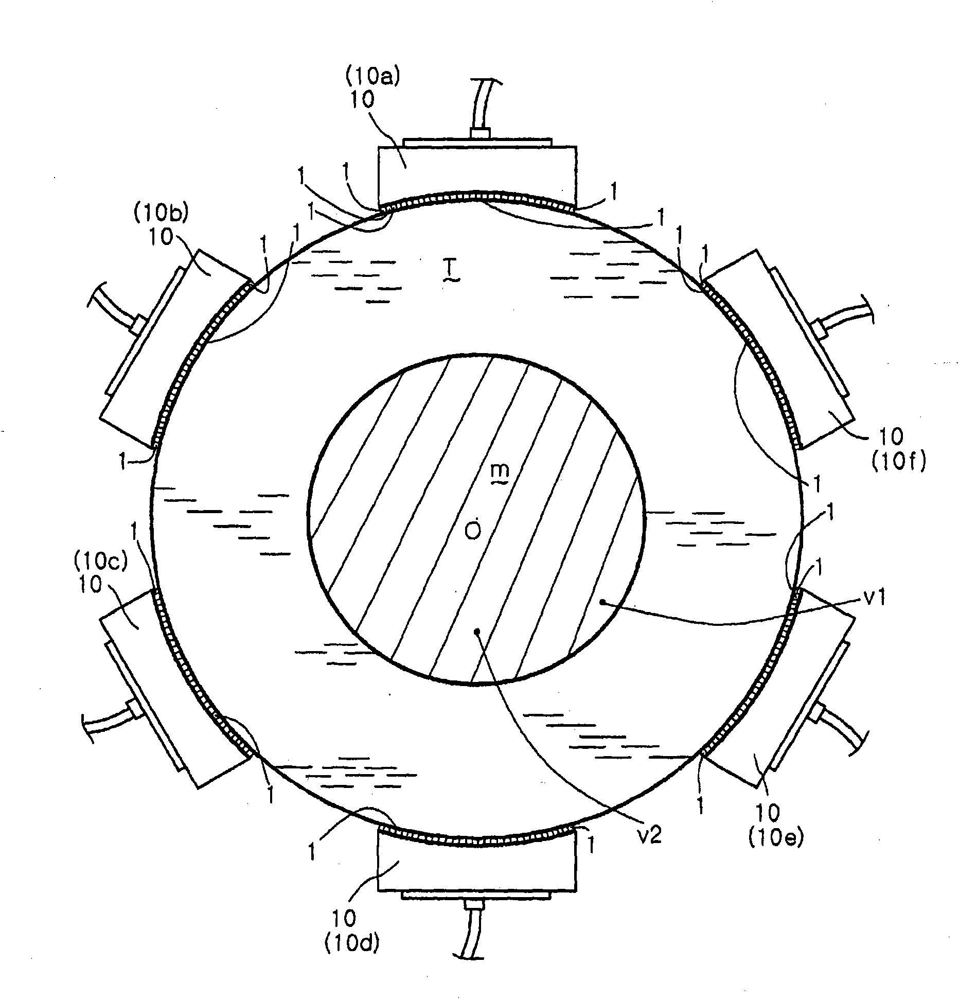
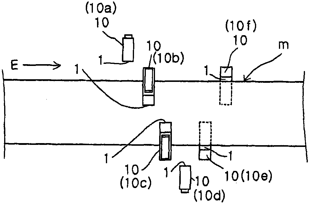
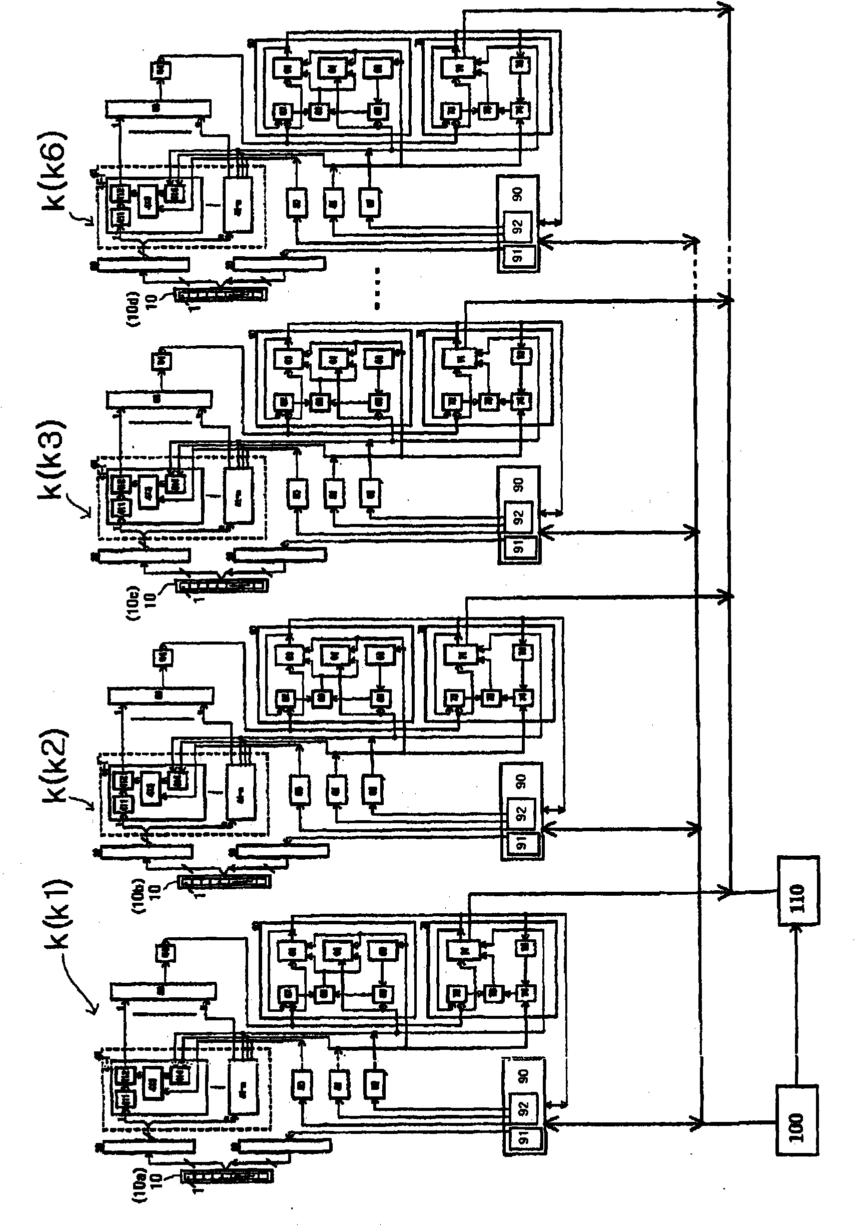
[0116] figure 1 It is a schematic cross-sectional view showing the arrangement of an array probe of a device according to an embodiment of the present invention. figure 2 It is a schematic side view showing the above arrangement. image 3 is the block diagram of the device. Figure 4 is enlarged image 3 The block diagram of the main part of the block diagram. Figure 5 It is a schematic cross-sectional view showing the focal position of ultrasonic waves of one array probe of the above-mentioned device with respect to a test material. Image 6 It is a schematic longitudinal sectional view illustrating a plane wave in volume focusing of each steel sheet as an inspection object. Figure 7 It is a schematic longitudinal sectional view illustrating volume focusing in the present invention in ...


PUM


Abstract

An ultrasonic flaw detection device using a volume focus fault detection method is as follows. The device detects faults in the inside of an object to be tested having a substantially circular cross section, wherein resonators (1...1) are arranged like an arc along a circular formed by the object to be tested. Array probes (10...10) are arranged so as to surround the object using an oblique flaw detection method. The excitation means can detect faults of an object to be tested, and the excitation means causes the ultrasonic waves to be incident into the inside of the object through each of sections of incident sections by vibrating the plurality of the resonators once and to reach a section opposite to the incident section on the circumference of the circle formed by the object and causesa plurality of resonators to be incident into the inside of the object using another one-time vibration, and causes the incident ultrasonic waves to reach any one of neighboring sections adjacent to the opposite section.

Description

technical field [0001] The invention relates to an ultrasonic flaw detection method and a device thereof. Background technique [0002] Patent Document 1: Japanese Patent Laid-Open No. 2003-130859 [0003] Patent Document 2: Japanese Patent No. 3704065 [0004] Patent Document 3: Japanese Patent Laid-Open No. 2006-250873 [0005] Non-Patent Document 1: Murakami Joko, Dominic Burakonie, Miura Shunji, Murai Junichi, Nishitani Toyo: The 13th Ultrasonic Wave にょる Non-breaking Soil Review Lecture Collection, pp.33-38, (2006) [0006] Non-Patent Document 2: Yokono Yasukazu: Status Quo of Standardization of Fiesdoare UT, NDI Document 21776, pp.34-38 (2006) [0007] In the conventional flaw detection method using a single vibrator, in the case of internal flaw detection of a cylindrical bar, etc., it is necessary not only for the axial direction of the bar, but also for the section intersecting the axial direction, along the The vibrator mechanically scans the circumference of th...

Claims


Application Information

Patent Timeline
Patent Type & Authority Applications(China)
IPC IPC(8): G01N29/04
CPCG01N2291/2634G01N29/28G01N29/223G01N29/043G01N2291/106
Inventor 村井纯一D·布拉科尼耶
Owner NIPPON KURAUTO KUREEMAA FUERUSUTAA
Why Eureka
Try Eureka