Bending equipment of heat exchanger and method for manufacturing bending heat exchanger

A manufacturing method and heat exchanger technology, applied in the direction of heat exchange equipment, etc., can solve the problems of large investment, low production efficiency, low qualified rate of finished products, etc.

Active Publication Date: 2010-09-22
SANHUA HANGZHOU MICRO CHANNEL HEAT EXCHANGER
View PDF6 Cites 14 Cited by
  • Summary
  • Abstract
  • Description
  • Claims
  • Application Information

AI Technical Summary

Problems solved by technology

Using manual bending and twisting, the consistency of the bending size cannot be guaranteed, the overall stability of the heat exchanger after bending is difficult to control, the production efficiency is low, and large-scale production cannot be realized
[0004] In addition, it is easy to damage the welding coating on the flat tube during the bending and twisting process, and it is necessary to design specially designed equipment for assemb

Method used


Image

  • Bending equipment of heat exchanger and method for manufacturing bending heat exchanger
  • Bending equipment of heat exchanger and method for manufacturing bending heat exchanger
  • Bending equipment of heat exchanger and method for manufacturing bending heat exchanger

Examples


Embodiment Construction

[0030] Embodiments of the present invention are described in detail below, examples of which are shown in the drawings, wherein the same or similar reference numerals designate the same or similar elements or elements having the same or similar functions throughout. The embodiments described below by referring to the figures are exemplary only for explaining the present invention and should not be construed as limiting the present invention.

[0031] In the description of the present invention, the orientation or positional relationship indicated by the terms "longitudinal", "transverse", "up and down", "upper", "lower" etc. are based on the orientation or positional relationship shown in the drawings, and are only for the purpose of It is convenient to describe the invention without requiring that the invention must be constructed and operated in a particular orientation, and thus should not be construed as limiting the invention.

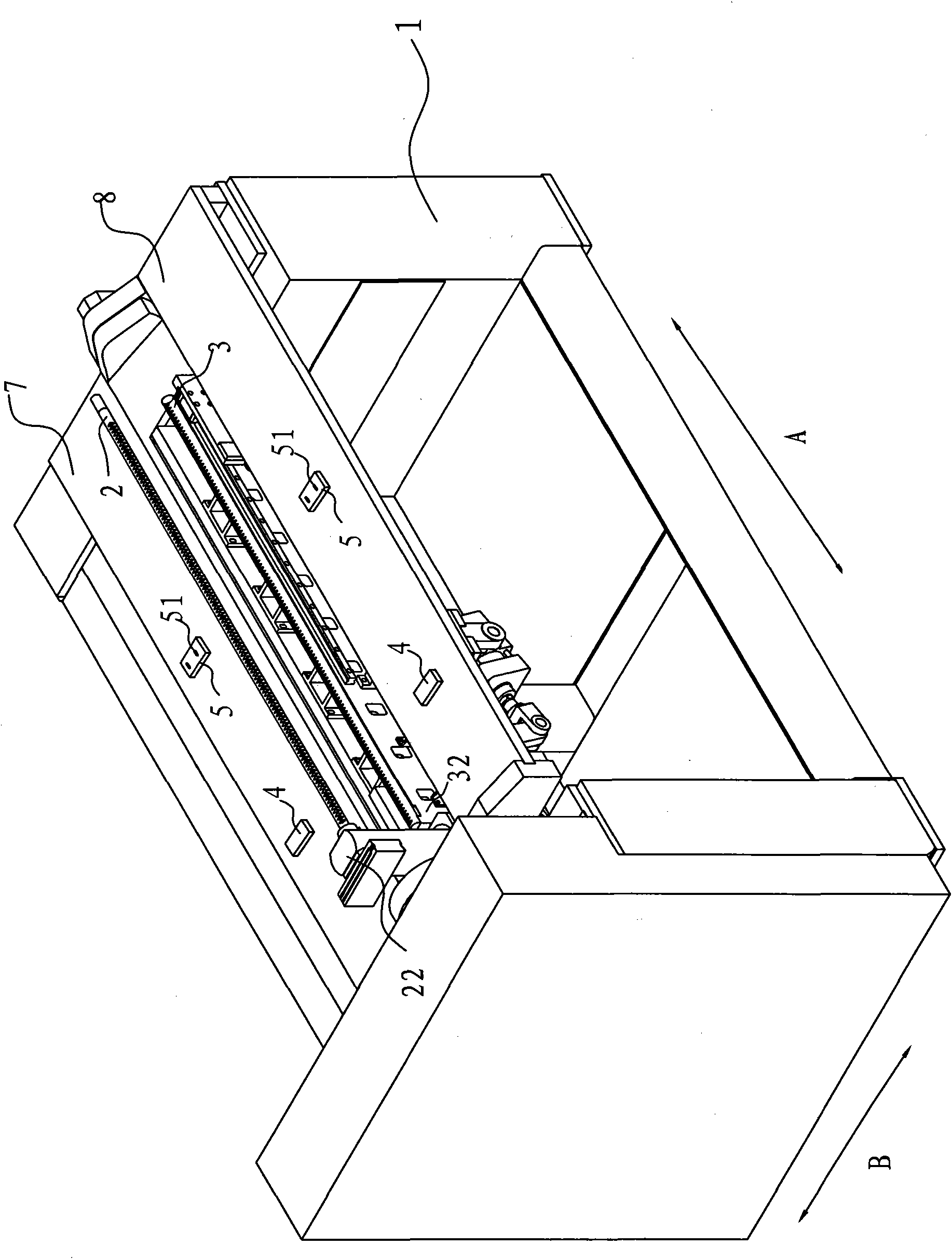
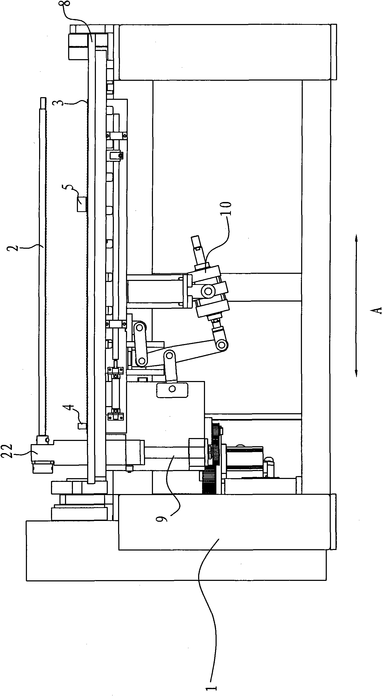
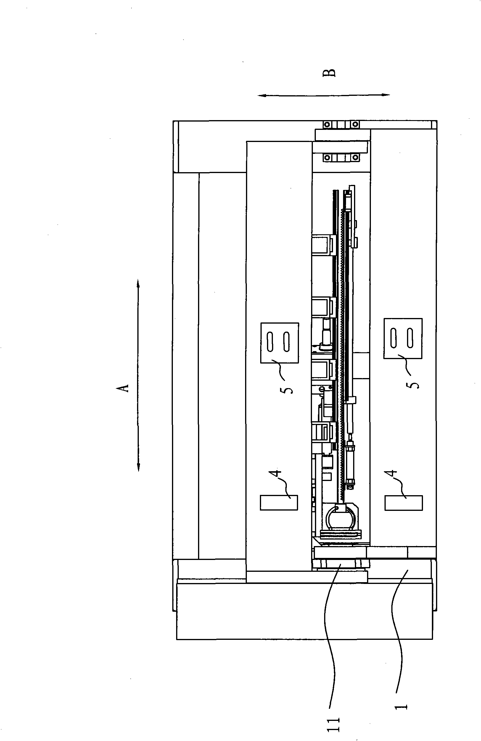
[0032] A heat exchanger bending device acco...


PUM


Abstract

The invention discloses bending equipment of a heat exchanger and a method for manufacturing a bending heat exchanger by utilizing the bending equipment. The bending equipment comprises a stand, an upper core shaft, a lower core shaft, a first bending plate and a second bending plate, wherein the upper core shaft is installed on the stand along the longitudinal direction of the stand, a plurality of upper grooves which are arranged along the longitudinal direction and are respectively provided with a downward opening are formed on the peripheral surface of the upper core shaft, the lower core shaft is installed on the stand along the longitudinal direction, a plurality of lower grooves which are arranged along the longitudinal direction and are respectively provided with an upward opening are formed on the peripheral surface of the lower core shaft, the plurality of lower grooves align with the plurality of upper grooves one by one in the vertical direction, the first bending plate and the second bending plate are respectively arranged at both transverse sides of the stand and can overturn, and at least one of the upper core shaft and the lower core shaft can move to twist a flat tube of the heat exchanger. Based on the bending equipment of the heat exchanger, all the flat tubes can be simultaneously twisted and bended in one step after the flat tubes, fins and collecting tubes are assembled and welded, and therefore, the consistency of the bending sizes and the stability of the whole bended heat exchanger are ensured and the production efficiency is enhanced.

Description

technical field [0001] The present invention generally relates to a bending device of a heat exchanger and a manufacturing method of a bent heat exchanger, and in particular to a bending device of a microchannel heat exchanger and a manufacturing method of a bent microchannel heat exchanger . Background technique [0002] The parallel flow heat exchanger can be formed into various shapes after bending to improve its heat transfer performance and can be applied to various special installation environments. [0003] Traditionally, the twisting and bending of the flat tubes of the heat exchanger is done manually, and each flat tube is twisted individually, and then the flat tubes are assembled and welded with fins and headers. Manual bending and twisting cannot guarantee the consistency of the bending size, the overall stability of the bent heat exchanger is difficult to control, the production efficiency is low, and large-scale production cannot be realized. [0004] In addi...

Claims


Application Information

Patent Timeline
IPC IPC(8): B21D11/14B21D53/06
Inventor 董长盛
Owner SANHUA HANGZHOU MICRO CHANNEL HEAT EXCHANGER
Why Eureka
Try Eureka