Air conditioner and wind direction control method thereof

A control method and air-conditioning technology, applied in air-conditioning systems, airflow control components, space heating and ventilation, etc., can solve the problems of short spray distance, involvement in air inlets, short-circuit air paths, etc., to increase the delivery distance, Improve heat exchange efficiency and prevent airflow backflow

Active Publication Date: 2010-09-22
HAIER GRP CORP +1
View PDF6 Cites 43 Cited by
  • Summary
  • Abstract
  • Description
  • Claims
  • Application Information

AI Technical Summary

Problems solved by technology

[0008] A single guide plate is used to control the upper and lower airflow. Since the width of the guide plate is narrow, the air duct formed by the air flow at the air outlet is relatively short, and the kinetic energy of the air flow at the air outlet of the guide plate is small, so the spraying distance is short. In the space far away from the air conditioner The comfort is poor; on the other hand, when cooling (heating), due to the short air duct, the cold (hot) air at the air outlet is easily drawn into the air inlet for the second time, that is, the air short circuit occurs
[0009] Double guide plates are used to control the upper and lower airflow. Although the overall width of the guide plates is lengthened, the short circuit of the air path and the spraying distance can be improved to a certain extent, but because the width of the upper guide plate is not lengthened, the airflow after spraying is still close to the air inlet. There will be a certain degree of air short circuit phenomenon

Method used


Image

  • Air conditioner and wind direction control method thereof
  • Air conditioner and wind direction control method thereof
  • Air conditioner and wind direction control method thereof

Examples


Embodiment Construction

[0032] The present invention will be described below in conjunction with the accompanying drawings and various embodiments.

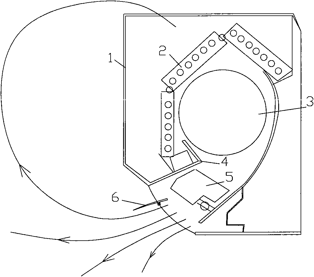
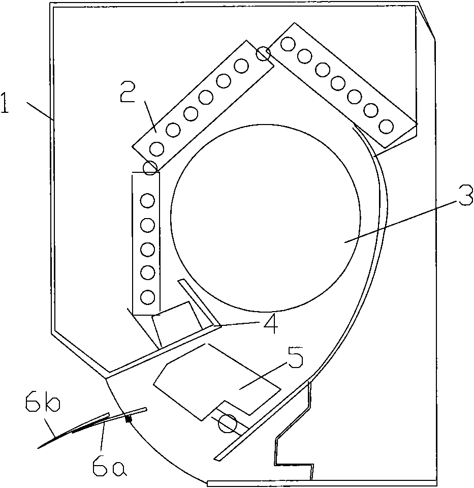
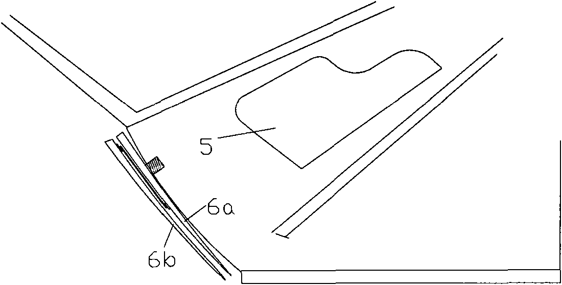
[0033] figure 1 A schematic diagram of the internal structure of an existing household air conditioner is shown. As shown in the figure, the on-hook air conditioner usually has a heat exchanger 2, a fan 3, a housing 4 forming an air outlet duct, a left and right air deflector 5 located in the air outlet that can swing left and right, and a vertical guide plate located in the air outlet that can swing up and down The wind deflector 6 is outside the casing 1 of the heat exchanger 2 . When heating (cooling), the indoor air enters the inside of the on-hook from the cover 1, is exchanged by the heat exchanger 2, and is blown out from the air outlet by the fan 3, and the left and right air guide plates 5 and the upper and lower air guides The plate 6 swings to change the airflow direction. However, it can be found that part of the airflow flowing out from ...


PUM


Abstract

The invention discloses an air conditioner, comprising a hang-up, wherein the air outlet of the hang-up is provided with an air deflector which can swing along the vertical direction and has adjustable extension width. The invention also discloses a wind direction control method of the air conditioner, comprising the following steps: enabling the air deflector to rotate at the vertical direction of the air outlet and enabling the air deflector to be in a width extension state; and enabling the air deflector width to be shrunk and closing the air outlet when the air conditioner is closed. The air conditioner in the invention can improve air path short circuit phenomenon, enhance heat exchange efficiency, increase airflow injection distance and boost air conditioner comfort. By the method in the invention, airflow reflux can be effectively prevented when the air conditioner is in use, and the air deflector width can be shrunk so as to close the air outlet when the air conditioner is closed, thus preventing foreign matters from entering and having elegant appearance.

Description

technical field [0001] The invention relates to the technical field of air conditioners, in particular to an air conditioner and a wind direction control method thereof. Background technique [0002] Among home appliances, air conditioners consume the most electricity. Among energy-saving measures for air conditioners, the improvement of the efficiency of compressors and heat exchangers has reached the limit of technology. It is becoming more and more important to achieve energy saving by improving airflow control. On the other hand, with the improvement of people's living standards, people's requirements for the comfort of room heating and cooling have become higher and higher. A big problem facing the industry. [0003] The method of achieving energy saving by improving airflow control is currently a field of vigorous development in the industry, such as the patent proposal with the publication number CN1283770A: by dividing the up and down swing guide plate into three, t...

Claims


Application Information

Patent Timeline
Patent Type & Authority Applications(China)
IPC IPC(8): F24F1/00F24F13/10
Inventor 何政保李明劳春峰
Owner HAIER GRP CORP
Why Eureka
Try Eureka