
High-efficiency module back-stroke displacement heat exchanger

A volumetric, heat exchanger technology, applied in the direction of heat exchanger types, heat exchanger shells, indirect heat exchangers, etc., can solve problems such as extremely high requirements for civil engineering and load capacity, heavy equipment operation weight, and complex installation process. , to achieve the effect of low maintenance cost, high pressure bearing capacity, and easy maintenance and management

Active Publication Date: 2010-09-22
西安华广电站锅炉有限公司
View PDF5 Cites 2 Cited by
  • Summary
  • Abstract
  • Description
  • Claims
  • Application Information

AI Technical Summary

Problems solved by technology

[0010] G. The installation process is complicated, the requirements for civil engineering and load capacity are extremely high, and the equipment is heavy in operation, which is not easy to install

Method used


Image

  • High-efficiency module back-stroke displacement heat exchanger
  • High-efficiency module back-stroke displacement heat exchanger
  • High-efficiency module back-stroke displacement heat exchanger

Examples


Embodiment Construction

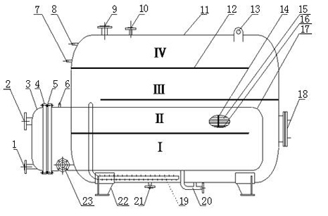
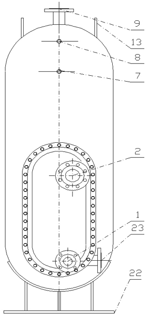
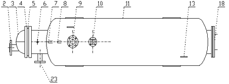
[0042] Such as figure 1 As shown, the high-efficiency module return volumetric heat exchanger includes the primary heat medium inlet flange 2 and the primary heat medium outlet flange 1 connected by the outer pipeline, including the primary heat medium inlet flange 2 and the primary heat medium The tube sheet 5 at the entrance of the outlet flange 1, the fixed heat exchange tube 15 of the tube sheet 5 extends horizontally to the chamber cylinder 17, and is characterized in that it also includes a cylinder 11 with holes on one side of the cylinder 11, and the holes make The chamber cylinder 17 extends horizontally into the cavity of the cylinder 11. In the cavity of the cylinder 11, return partitions 12 are arranged horizontally above and below the chamber cylinder 17 to form multiple return mixing chambers. The horizontal chambers The cylinder body 17 communicates with the vertical cylinder body 11 through a porous radiant tube 19. When working, the primary heat medium enters ...


PUM


Abstract

The invention relates to a heater exchanger, in particular to a high-efficiency module back-stroke displacement heat exchanger which is characterized by also comprising a cylinder. One side of the cylinder is provided with an open hole which enables chamber cylinders to horizontally extend into the cavity of the cylinder. Back stroke partition plates are vertically and horizontally arranged at intervals above the chamber cylinder in the cavity of the cylinder to form a plurality of back stroke mixing chambers, and horizontal chamber cylinders and vertical cylinders are communicated with each other through porous radiant tubes. When in working, primary fluid enters an end socket from a primary fluid inlet flange, flows through a horizontal heat exchange tube extending into the end socket, and flows out from the outlet of the heat exchange tube extending into the end socket and the primary fluid outlet flange through back strokes partitioned by a U-shaped heat exchange tube and an end socket partition plate. Secondary fluid flows through a secondary fluid inlet flange at the lower end of the chamber cylinder at the outer side of the cylinder, and is sufficiently mixed and stirred through a back stroke mixing chamber, back stroke is carried out, and the secondary fluid subjected to the treatment is discharged from a secondary fluid outlet flange on the upper end of the cylinder. The invention provides the high-efficiency module back-stroke displacement heat exchanger which can improve the thermal efficiency, the energy utilization rate and the water yield, reduce the cost andreduce the architectural space, is convenient to maintain and clean, and has simple manufacturing process.

Description

technical field [0001] The invention relates to a heat exchanger, in particular to a high-efficiency module return volume heat exchanger. Background technique [0002] In the prior art, volumetric heat exchangers mainly include: RV series volumetric heat exchangers, which are divided into two types: vertical and horizontal. The existing vertical and horizontal volumetric heat exchangers combine heat exchange tubes with The tube plate is connected, and then inserted into the shell of the volumetric heat exchanger by welding; the stroke of the primary heat medium and the secondary heat medium is too short, and the secondary heat medium is basically in the static heating in the volume tank, so heat transfer cannot be realized Convective heat transfer in science, so the utilization rate of heat medium is extremely low, only about 50%, which wastes a lot of available heat and increases the cost. The volume utilization rate is not high, and there are dead water areas, the water ou...

Claims


Application Information

Patent Timeline
Patent Type & Authority Applications(China)
IPC IPC(8): F28D7/00F28F9/22F28F27/00
Inventor 冉昭杰师晓娟汪宗海冉东成冉东汶
Owner 西安华广电站锅炉有限公司
Learn More