
Resistance measurement device of conduction cooling type superconduction adapter

A technology of superconducting joints and resistance measurement, which is applied in the direction of measuring devices, measuring electrical variables, measuring magnetic variables, etc.

Inactive Publication Date: 2010-09-22
INST OF ELECTRICAL ENG CHINESE ACAD OF SCI
View PDF2 Cites 18 Cited by
  • Summary
  • Abstract
  • Description
  • Claims
  • Application Information

AI Technical Summary

Problems solved by technology

[0007] In order to overcome the shortcomings of the traditional superconducting joint resistance measuring device, the present invention proposes a conduction cooling superconducting joint resistance measuring device

Method used


Image

  • Resistance measurement device of conduction cooling type superconduction adapter
  • Resistance measurement device of conduction cooling type superconduction adapter
  • Resistance measurement device of conduction cooling type superconduction adapter

Examples


Embodiment Construction

[0018] The present invention will be further described below in conjunction with the accompanying drawings and specific embodiments.

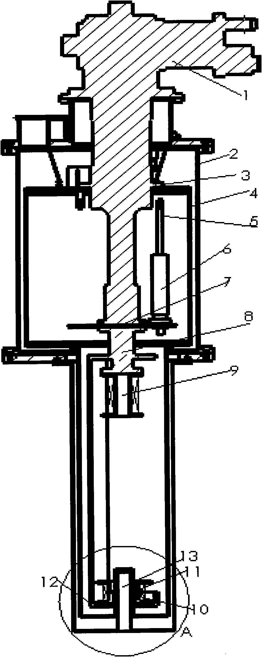
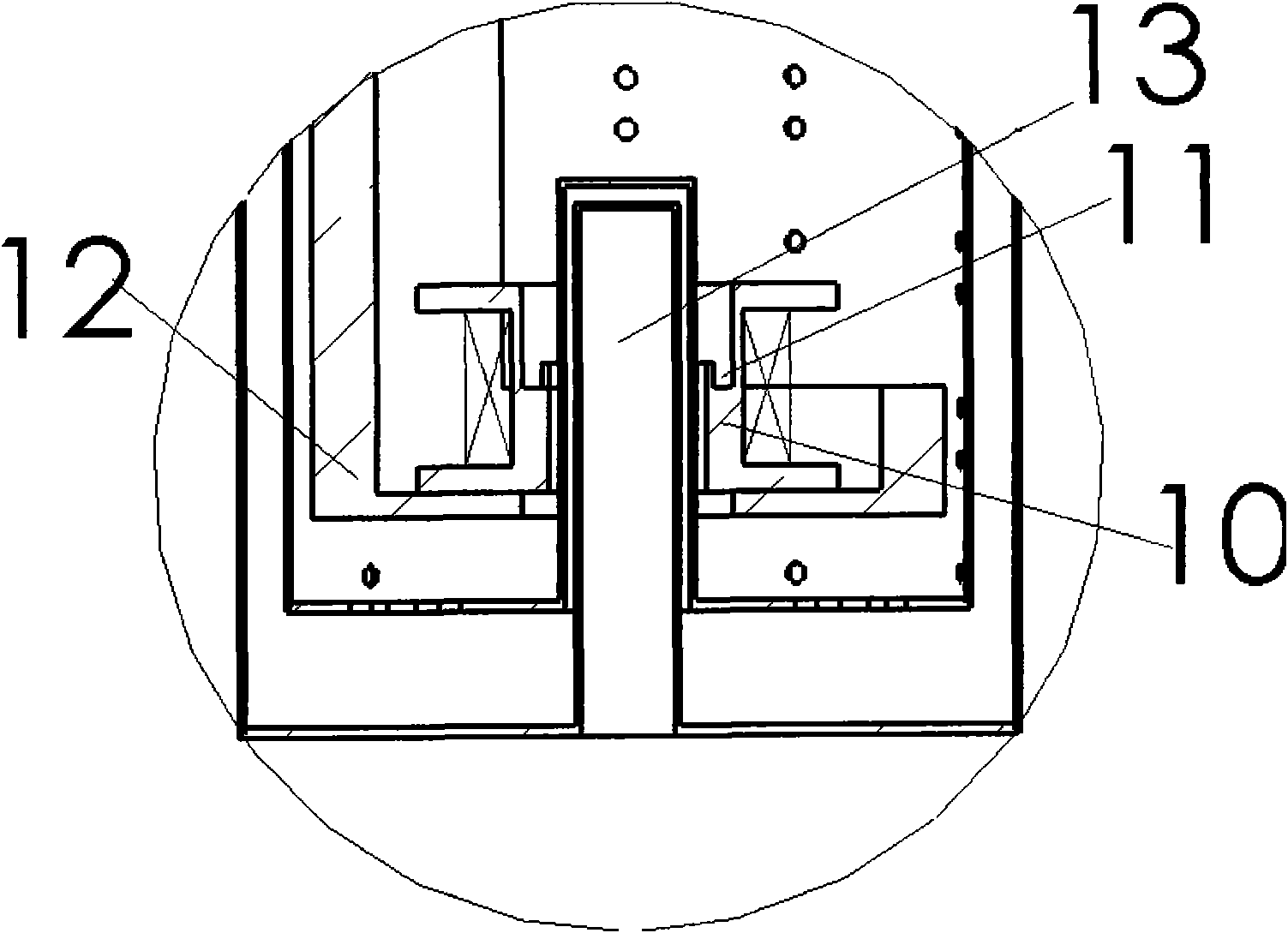
[0019] Such as figure 1 and figure 2 As shown, the superconducting joint resistance measuring device of the present invention mainly includes a cryogenic system and a sample chamber. The cryogenic system consists of an outer vacuum container 2 , a GM refrigerator 1 , a 40K heat radiation screen 4 and a heat conduction structure 8 . The sample chamber is wrapped in a 40K thermal radiation shield 4 to reduce the radiation heat leakage from the outside to the sample chamber; the primary cold head 3 of the GM refrigerator 1 passes through the outer vacuum container 2 to connect with the 40K thermal radiation shield 4 and provides cooling capacity to The 40K thermal radiation screen 4 is cooled to about 40K; the secondary cold head 7 of the GM refrigerator 1 passes through the 40K thermal radiation screen 4 and is thermally connected to the sampl...


PUM


Abstract

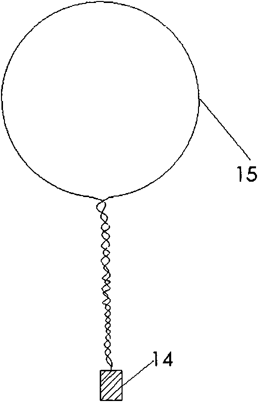
The invention relates to a resistance measurement device of a conduction cooling type superconduction adapter, which comprises a cryogenic system and a sample chamber. The sample chamber comprises a back field superconducting magnet (9), a superconducting mutual inductor (10) and a sample cell (11) which are all arranged inside a thermal radiation screen (4) of 40k and are connected and fixed on a secondary cooling head (7) of a GM refrigerating machine (1) by a heat conduction structure (8). A single-turn closed ring (15) of a sample is embedded in the sample cell (11), and a superconductionadapter (14) is arranged in the center of an inner hole of the back field superconducting magnet (9). Current with a certain magnitude is induced to the single-turn closed ring (15) by the superconducting mutual inductor (10), then the magnitude of a center magnetic field of the single-turn closed ring (15) is measured by utilizing a room-temperature hole (13) in the center of a lower bottom plate of a vacuum container (2) at the outside through using a conventional Hall probe, the magnitude of the current in the single-turn closed ring (15) is calculated, and the actual resistance value of the superconduction adapter can be calculated by measuring the current values of two different time points.

Description

technical field [0001] The present invention relates to a pair of superconducting wires (such as Nb 3 Sn superconducting wire and Nb 3 Sn superconducting wire, Nb 3 A device for measuring the resistance of superconducting joints made of electrical connections between Sn superconducting wires and NbTi superconducting wires, or between NbTi superconducting wires and NbTi superconducting wires. Background technique [0002] We know that superconducting magnets, especially large and medium-sized superconducting magnets, are generally composed of many superconducting coils connected in series. Due to the limitation of the length of commercially supplied superconducting wires or the different requirements of superconducting coils on superconducting wire parameters and the needs of magnet winding process, it is impossible for each superconducting coil in a superconducting magnet to be wound with the same superconducting wire. Superconducting wires must be welded with resistance ...

Claims


Application Information

Patent Timeline
Patent Type & Authority Applications(China)
IPC IPC(8): G01R27/02G01R33/07
Inventor 陈顺中王晖崔春燕
Owner INST OF ELECTRICAL ENG CHINESE ACAD OF SCI
Learn More