
Power supply circuit for improving transient variation reaction, control circuit and method thereof

A power supply circuit, instantaneous change technology, applied in the direction of electrical components, output power conversion devices, etc., can solve problems such as inability to use and application

Inactive Publication Date: 2010-09-22
RICHTEK TECH
View PDF1 Cites 17 Cited by
  • Summary
  • Abstract
  • Description
  • Claims
  • Application Information

AI Technical Summary

Problems solved by technology

This case is not aimed at solving the problem of instantaneous changes in input voltage. Its purpose is mainly to solve the problem of circuit reaction efficiency when the reference voltage Vref changes under the circuit structure where the reference voltage Vref is variable. The method cannot be applied to the reference voltage Vref. Under the immutable structure, and the method of directly superimposing the reference voltage Vref in this case can only be applied to the step-down power supply circuit, and cannot be applied to other types of power supply circuits such as boost type and reverse voltage type.

Method used


Image

  • Power supply circuit for improving transient variation reaction, control circuit and method thereof
  • Power supply circuit for improving transient variation reaction, control circuit and method thereof
  • Power supply circuit for improving transient variation reaction, control circuit and method thereof

Examples


Embodiment Construction

[0048] Please refer to Figure 8 , which shows a first embodiment of the invention. In the present invention, the instantaneous change value ΔV of the input voltage IN is obtained by the input voltage instantaneous change extraction circuit (ΔV·K) 21, and converted into an appropriate ratio (K times, K can be any positive or negative real number, and its absolute value can be greater than , equal to or less than 1), it is directly superimposed to the output terminal of the error amplifier EA 22 to quickly respond to changes in the input voltage.

[0049] In detail, such as Figure 8 As shown, the power supply circuit for improving transient change response in this embodiment includes an error amplifier (EA) 12, a pulse width modulation comparator 14, a drive circuit 16, an input voltage transient change extraction circuit 21, and a power stage 28, except Circuits other than the power stage 28 constitute the control circuit 20 . The power stage 28 converts the input voltage IN...


PUM


Abstract

The invention relates to a power supply circuit for improving transient variation reaction, a control circuit and a method thereof. The power supply circuit for improving transient variation reaction comprises a power level circuit, an error amplifier, an input voltage transient variation extraction circuit and a pulse width modulation (PWM) comparator, wherein the power level circuit comprises at least one power transistor switch, an input voltage is converted into an output voltage by the switching of the power transistor switch; the error amplifier is used for comparing a feedback signal related with the output voltage with a reference signal to generate an error amplifying signal; the input voltage transient variation extraction circuit is used for extracting transient variation of the input voltage and generating a signal related with the transient variation; and the PWM comparator at least generates a PWM signal according to a saw wave signal, the error amplifying signal and the signal related with the transient variation so as to control the power transistor switch in the power level circuit.

Description

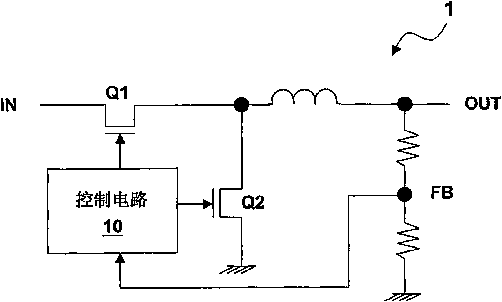
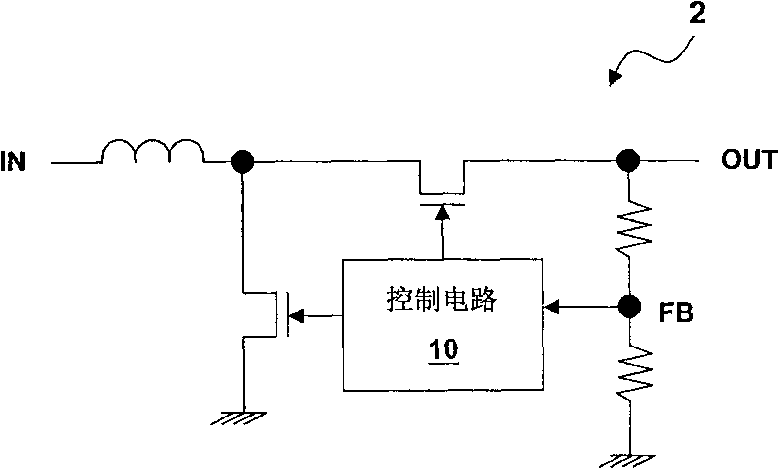
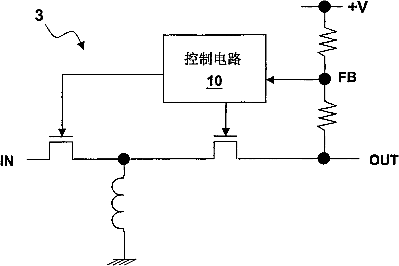
technical field [0001] The present invention relates to a power supply circuit for improving instantaneous change response, its control circuit and method. Background technique [0002] There are many types of power supply circuits, such as Buck Converter, Boost Converter, Inverter Converter, Buck-Boost Converter, and Fly Back Converter) and so on. First, take the step-down power supply circuit as an example to illustrate, and its circuit structure is roughly as follows: figure 1 As shown, the step-down power supply circuit 1 includes two power transistor switches Q1 and Q2, which are controlled by the control circuit 10; the control circuit 10 generates a switch control signal to control the transistor Q1 according to the feedback voltage signal FB extracted from the output terminal. , On and off of Q2, so as to transmit electric energy from the input terminal IN to the output terminal OUT. figure 2 Mark the step-up power supply circuit 2, image 3 Mark the reverse pre...

Claims


Application Information

Patent Timeline
IPC IPC(8): H02M1/00
Inventor 詹爵魁林水木
Owner RICHTEK TECH
Learn More