Device and method for detecting heat-dissipating plate

A detection device and detection method technology, applied in the direction of measurement device, electrical device, radiation pyrometry, etc., to achieve the effect of improving product yield

Inactive Publication Date: 2010-09-15
陈文进 +2
View PDF0 Cites 13 Cited by
  • Summary
  • Abstract
  • Description
  • Claims
  • Application Information

AI Technical Summary

Problems solved by technology

[0006] The purpose of the present invention is to solve the problem of rapid and large-scale detection of existing heat sinks.

Method used


Image

  • Device and method for detecting heat-dissipating plate
  • Device and method for detecting heat-dissipating plate
  • Device and method for detecting heat-dissipating plate

Examples


Embodiment Construction

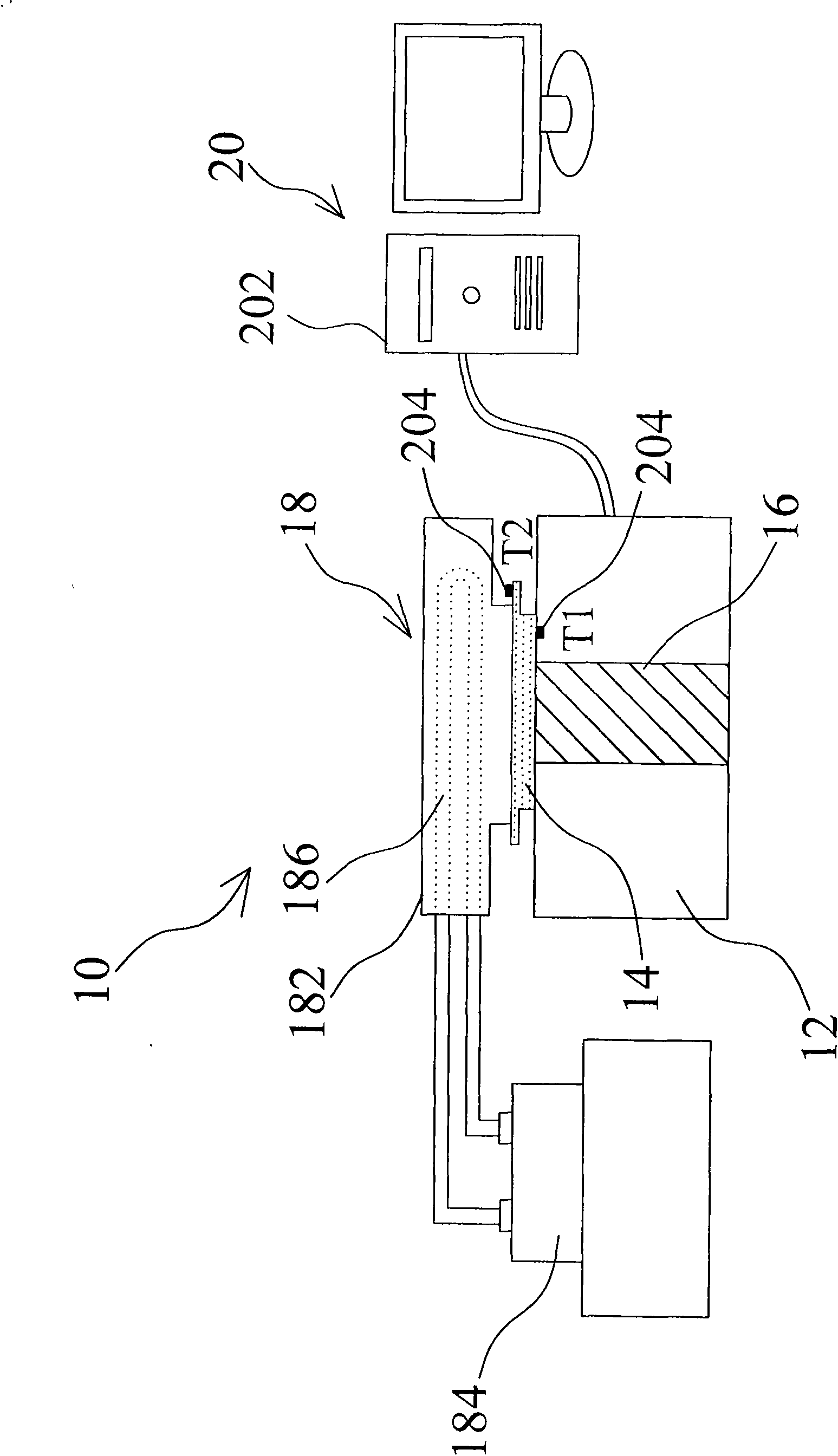
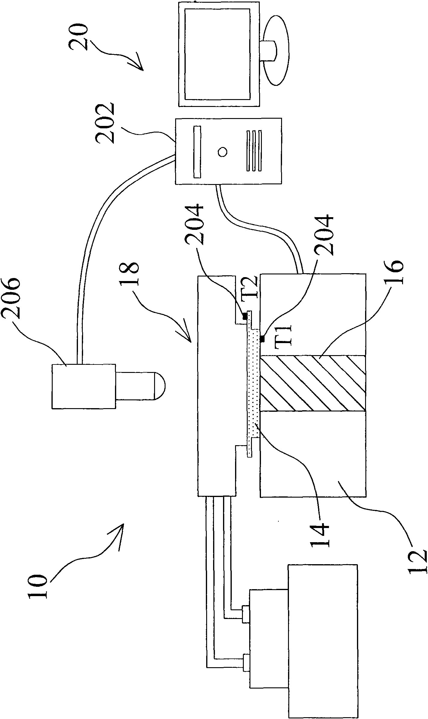
[0016] figure 1 It is a schematic diagram of the structure of the heat dissipation plate detection device of the present invention. As shown in the figure, the present invention is a heat dissipation plate detection device 10, including a detection platform 12, and the detection platform 12 is mainly for placing a thermal conductor 14. In this embodiment, the thermal conductor It is a vapor chamber; a heat source 16, the heat source 16 can provide heat energy, and is in contact with the heat conductor 14, the heat source 16 can make point contact or surface contact with the heat conductor 14, and the heat source 16 can be a light-emitting diode or an electric heating rod, etc., which can release heat energy Device; a heat dissipation device 18, which is in contact with the heat conductor 14, and can quickly remove the heat on the heat conductor 14. The heat dissipation device 18 can be a condensation rod, an air conditioner, a heat dissipation fan, an aluminum heat dissipation ...


PUM


Abstract

The invention discloses a device and a method for detecting a heat-dissipating plate. The device for detecting the heat-dissipating plate comprises a detecting platform, a heat source, a heat sink device and a data recorder, wherein the detecting platform is provided with a heat conductor; the heat source provides heat energy and is contacted with the heat conductor; the heat sink device is contacted with the heat conductor and removes the heat from the heat conductor rapidly; the data recorder comprises an infrared thermal imaging system and a calculating device; and the data recorder is used for acquiring and analyzing temperature data and can detect the heat flux of the heat conductor accurately and rapidly. The invention also provides the method for detecting the heat-dissipating plate; a mechanism for rapidly detecting the yield of the heat conductors is established so as to improve the yield of products more accurately; and the device and the method are suitable for the detection of mass production.

Description

technical field [0001] The invention relates to a detection device and a detection method, in particular to a heat dissipation plate detection device and a detection method. Background technique [0002] At present, the design focus of electronic products is light, thin and small. With the reduction of volume, the space of the chip is compressed to be smaller and narrower, and the heat emitted by the relative unit volume is also increased proportionally. Take the central processing unit of a computer as an example, the thermal energy has increased by five times in ten years. But it is a pity that the current traditional heat dissipation components still cannot remove the heat energy of the increased power of the central processing unit in time after the volume is reduced. In addition to increasing the fan size and speeding up the speed, the current heat dissipation methods can only make a fuss about the design of the heat dissipation fins. The effects of the above heat diss...

Claims


Application Information

Patent Timeline
Patent Type & Authority Applications(China)
IPC IPC(8): G01N25/20G01J5/00G01K7/02
Inventor 陈文进陈志朗陈坤川
Owner 陈文进
Why Eureka
Try Eureka