Controllable LED load current driving circuit

A technology of drive circuit and load current, applied in the direction of lamp circuit layout, electric light source, lighting device, etc., can solve the problems of failure, affecting the reliability and life of LED, etc.

Inactive Publication Date: 2010-09-22
NINGBO LONGYUAN ILLUMINATE APPLIANCE
View PDF2 Cites 4 Cited by
  • Summary
  • Abstract
  • Description
  • Claims
  • Application Information

AI Technical Summary

Problems solved by technology

The light output of the LED is directly related to the LED current, so when the input voltage and ambient temperature of the LED drive circuit change, the light output of the LED will change with the input voltage and temperature, and if the LED current Out of control, the long-term operation of the LED under high current will affect the reliability and life of the LED, and may fail

Method used


Image

  • Controllable LED load current driving circuit
  • Controllable LED load current driving circuit
  • Controllable LED load current driving circuit

Examples


Embodiment Construction

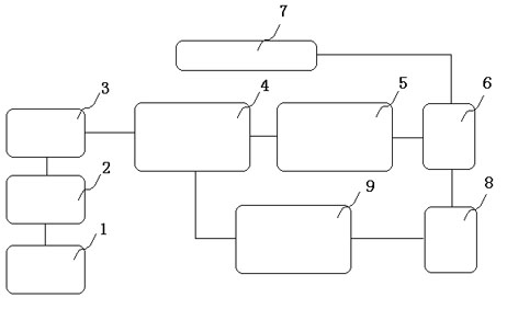
[0026] Such as figure 1 As shown, a controllable LED load current drive circuit at least includes: EMC and surge current control circuit 2, primary rectification and filter circuit 3, single-ended flyback DC / DC power converter 4, secondary rectification and The filter circuit 5 and the constant current and constant voltage output circuit 6, the constant current and constant voltage output circuit 6 are electrically connected to the two electrodes of the LED array 7, the constant current and constant voltage output circuit 6 and the single-ended flyback DC / DC power Between the converters 4 are connected an overcurrent, overvoltage, overheating and undervoltage signal sampling circuit 8 and an overcurrent, overvoltage, overheating and undervoltage protection circuit 9, and an overcurrent, overvoltage, overheating and undervoltage signal sampling circuit 8 The extracted voltage fluctuation signal passes through the current, overvoltage, overheating and undervoltage protection cir...


PUM


Abstract

The invention belongs to a power supply of an illumination light source, in particular to a controllable LED load current driving circuit, which is characterized in that: an over-current, over-voltage, over-heat and under-voltage signal sampling circuit and an over-current, over-voltage, over-heat and under-voltage protection circuit are connected between a constant-current and constant-voltage output circuit and a single-ended flyback DC/DC power converter; a voltage fluctuation signal extracted by the over-current, over-voltage, over-heat and under-voltage signal sampling circuit passes through the over-current, over-voltage, over-heat and under-voltage protection circuit and then controls the output of the single-ended flyback DC/DC power converter, so that the constant-current and constant-voltage output circuit outputs stable voltage and current; and the over-current, over-voltage, over-heat and under-heat protection circuit adopts a current control mode PWM/PFM generator. In the invention, the controllable LED load current driving circuit is provided, has high power and high reliability and is slightly changed with factors, such as input voltage, temperature and the like.

Description

technical field [0001] The invention belongs to a power supply of an illumination light source, in particular to a drive circuit for a controllable LED load current. Background technique [0002] LED is a solid light source. When a forward voltage is applied to both ends of the LED, the minority carriers and majority carriers in the semiconductor recombine, and the excess energy released will cause photon emission. Light-emitting diodes of different colors can be made by using different materials. As a new light source, in recent years, major companies and research institutions have been doing research on LEDs, which has greatly improved their luminous efficiency. Lumiled has developed and produced white LEDs with a luminous efficacy of 90Lm / W, which has reached the level of incandescent lamps. s level. [0003] Compared with incandescent lamps, LEDs have many advantages in terms of performance: [0004] See the table below: [0005] Table 1 Performance comparison of inc...

Claims


Application Information

Patent Timeline
Patent Type & Authority Applications(China)
IPC IPC(8): H05B37/02
Inventor 俞才龙王水平
Owner NINGBO LONGYUAN ILLUMINATE APPLIANCE
Why Eureka
Try Eureka