Gate valve device

A gate valve and spool technology applied in the field of gate valve devices to achieve the effect of easy power supply

Inactive Publication Date: 2010-09-29
TOKYO ELECTRON LTD
View PDF3 Cites 12 Cited by
  • Summary
  • Abstract
  • Description
  • Claims
  • Application Information

AI Technical Summary

Problems solved by technology

However, in a gate valve device including a drive mechanism in which a valve body is connected to a base member via a link mechanism, the integrated valve body and the heater are separated from the base as the valve body moves to open and close the opening. The relative positional relationship between the members changes, so there is a problem that it is difficult to arrange the power supply cable to be connected to the heater via the base member and the link mechanism

Method used


Image

  • Gate valve device
  • Gate valve device
  • Gate valve device

Examples


no. 1 Embodiment approach

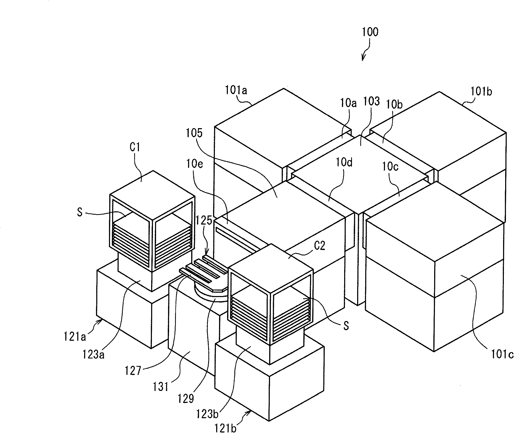
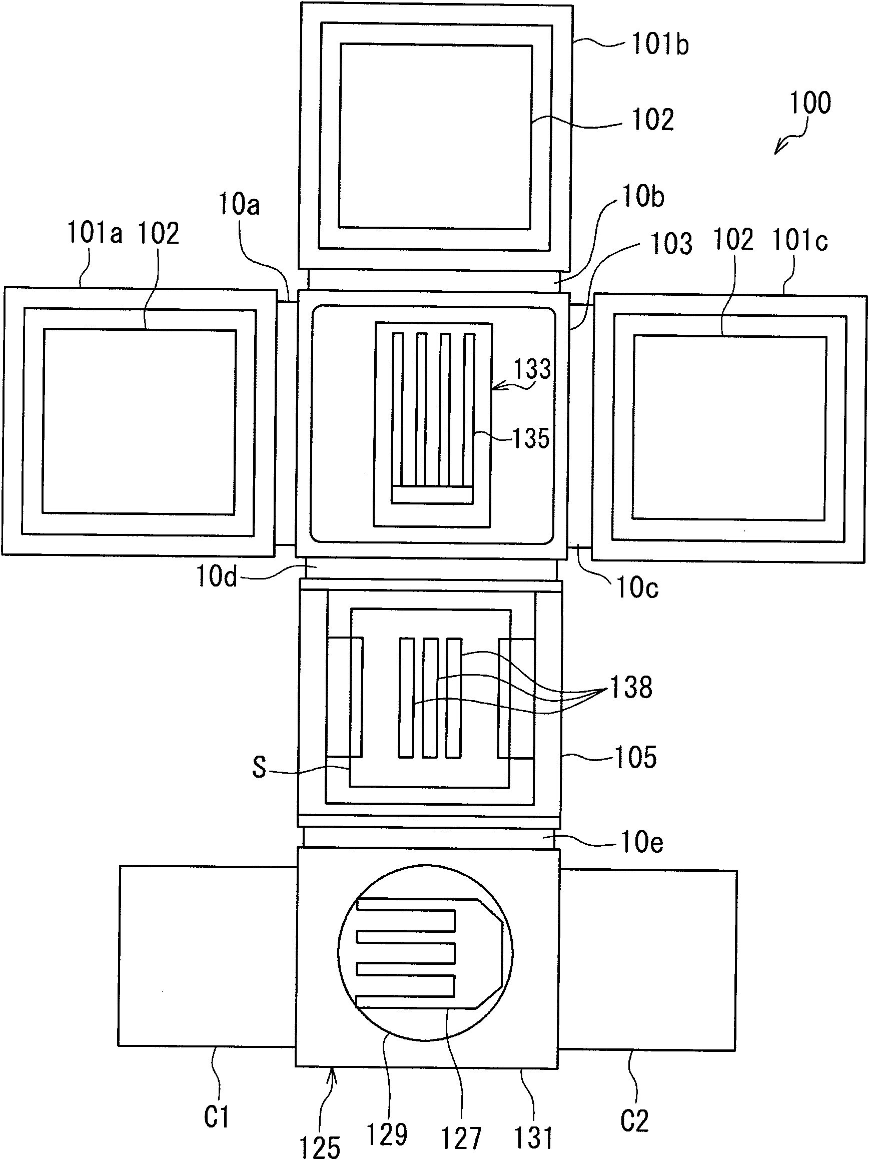
[0040] Hereinafter, embodiments of the present invention will be described in detail with reference to the drawings. First, refer to figure 1 and figure 2 , the configuration of a vacuum processing system 100 as an example of a system including the gate valve device according to the first embodiment of the present invention will be described. figure 1 It is a perspective view schematically showing the vacuum processing system 100 . figure 2 It is a top view schematically showing the inside of the vacuum processing system 100 . The vacuum processing system 100 is configured, for example, as a processing system for performing plasma processing on a glass substrate (hereinafter simply referred to as "substrate") S for FPD. Moreover, as FPD, a liquid crystal display (LCD), an electroluminescence (Electro Luminescence; EL) display, a plasma display panel (PDP), etc. are mentioned.

[0041] The vacuum processing system 100 has five vacuum chambers connected in a cross shape. ...

no. 2 Embodiment approach

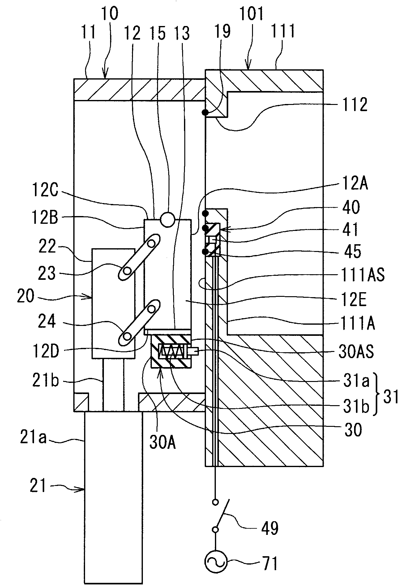
[0102] Below, refer to Figure 10 ~ Figure 12 , and a gate valve device according to a second embodiment of the present invention will be described. Figure 10 ~ Figure 12 It is a sectional view showing the structure of the gate valve device of this embodiment. in addition, Figure 10 Indicates the open state of the gate valve device, Figure 11 and Figure 12 Indicates the closed state of the gate valve device.

[0103] Differences between the gate valve device 80 of this embodiment and the gate valve device 10 of the first embodiment will be described below. The gate valve device 80 has a housing 81 instead of the housing 11 of the gate valve device 10 . The casing 81 has a box shape having an upper portion, a bottom portion, and four side portions connecting the upper portion and the bottom portion. One of the four side portions of the housing 81 is in contact with the wall 111A of the housing 111 of the chamber 101 . This side portion is referred to as a wall consti...

no. 3 Embodiment approach

[0116] Below, refer to Figure 13 ~ Figure 17 , and a gate valve device according to a third embodiment of the present invention will be described. Figure 13 ~ Figure 15 It is a sectional view showing the structure of the gate valve device of this embodiment. in addition, Figure 13 Indicates the open state of the gate valve device, Figure 14 and Figure 15 Indicates the closed state of the gate valve device. Figure 16 yes means Figure 14 It is a front view of the valve body, the heater, the connector part, the sub-connector part and the sub-terminal part of the gate valve device in the state shown. Figure 17 It is a circuit diagram showing the circuit configuration of the gate valve device of this embodiment.

[0117] The gate valve device 90 of the present embodiment includes a sub-connector part 50 and a sub-terminal part 60 in addition to the constituent elements of the gate valve device 10 of the first embodiment. The sub connector part 50 is integrated with t...


PUM


Abstract

The invention provides a gate valve device, which is provided with a heater on a valve core for opening and closing an opening part and can easily supply the power for the heater. The gate valve device (10) comprises a valve core (12) for opening and closing a opening part (112) arranged on a wall for spacing two adjacent spaces, a valve core moving device (20) for moving the valve core (12), a heater (13) for heating the valve core (12), and a connector electrically connected with the heater (13), and electrically connected and physically connected with a power output part for outputting the power for the heater (13). The valve core (12), the heater (13) and the connector are integrated, the connector is linked with the valve core (12) in the following mode: in the state that the valve core (12) closes the opening part (112), the connector is electrically connected and physically connected with the power output part, in the state that the valve core (12) opens the opening part (112), the connector is electrically separated and physically separated from the power output part.

Description

technical field [0001] The present invention relates to a gate valve device for opening and closing an opening, such as the opening of a vacuum chamber, which is provided on a wall separating two adjacent spaces. The substrate is processed under the conditions. Background technique [0002] A vacuum processing system is used to perform processes such as plasma etching, plasma ashing, and plasma film formation on substrates such as glass substrates for FPDs (Flat Panel Displays) under vacuum conditions. The vacuum processing system includes, for example: a processing chamber, which is used to process the substrate; a conveying chamber, which accommodates a conveying device for sending the substrate into the processing chamber and sending the substrate out of the processing chamber; a gate valve device, which is arranged in the processing chamber and the transfer chamber. Both the processing chamber and the transfer chamber are vacuum chambers for processing substrates under...

Claims


Application Information

Patent Timeline
Patent Type & Authority Applications(China)
IPC IPC(8): F16K49/00H01R13/66H01R13/70
Inventor 佐佐木和男锅山裕树
Owner TOKYO ELECTRON LTD
Why Eureka
Try Eureka