
Cup-shaped harmonic oscillator of cup-shaped fluctuated gyroscope and mechanical balancing method thereof

A technology of mechanical balance and harmonic oscillator, which is applied in the direction of speed measurement by gyro effect, gyroscope/steering sensing equipment, measuring device, etc. It can solve the problems of extremely high requirements for shape modification equipment, single shape modification means, and poor economy. , to achieve the effect of improving the modification efficiency, flexible operation and high economic benefit

Active Publication Date: 2010-09-29
NAT UNIV OF DEFENSE TECH
View PDF5 Cites 22 Cited by
  • Summary
  • Abstract
  • Description
  • Claims
  • Application Information

AI Technical Summary

Problems solved by technology

The traditional ordinary harmonic oscillator leveling is to remove a certain amount of vibrating part of the material at the edge of the harmonic oscillator. The smaller the material requirement, the more difficult the operation, the longer the adjustment time, and the lower the economy; and the balance method for the cup-shaped harmonic oscillator is still under study, and there is no relevant report

Method used


Image

  • Cup-shaped harmonic oscillator of cup-shaped fluctuated gyroscope and mechanical balancing method thereof
  • Cup-shaped harmonic oscillator of cup-shaped fluctuated gyroscope and mechanical balancing method thereof
  • Cup-shaped harmonic oscillator of cup-shaped fluctuated gyroscope and mechanical balancing method thereof

Examples


Embodiment

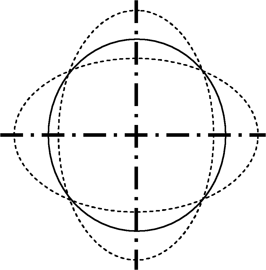
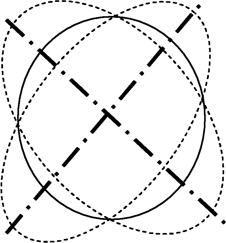
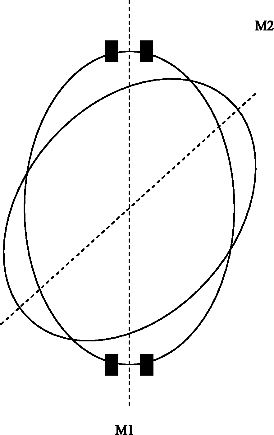
[0025] a kind of like Figure 7 , Figure 8 The cup-shaped resonator of the cup-shaped undulating gyroscope of the present invention shown, the cup-shaped resonator comprises a cylindrical side wall 1 and a circular chassis 2 ( The diameter of the chassis is 25mm), the side wall 1 includes a resonant ring 11 on the top and a vibration transmission part 12 on the bottom, a mounting base 21 is provided at the center of the chassis 2, and the resonant ring 11 is connected with the chassis 2 through the vibration transmission part 12. The top of the resonant ring 11 is evenly arranged with sixteen shaping grooves 3 (groove width 1 mm and groove depth 0.5 mm) along the circumferential direction, and eight shaping holes 4 (the diameter of the shaping holes are evenly arranged on the chassis 2 on the periphery of the mounting base 21 is 4.5mm). A piezoelectric electrode 5 is pasted between two adjacent modification holes 4 of the chassis 2, the vibration of the excited piezoelectri...


PUM


Abstract

The invention relates to a harmonic oscillator of a gyroscope and a balancing method thereof, in particular disclosing a cup-shaped harmonic oscillator of a cup-shaped fluctuated gyroscope and a mechanical balancing method. The cup-shaped harmonic oscillator comprises a side wall and a chassis fixedly connected to the bottom of the side wall, wherein the side wall comprises a harmonic oscillation ring at the upper part and an oscillation transfer part at the lower part, the center of the chassis is provided with an installation base, the top of the harmonic oscillation ring is uniformly distributed with modifying tanks are uniformly distributed on the top of the harmonic oscillation ring along a circumferential direction, and modifying holes are uniformly distributed on the chassis. The balancing method of the cup-shaped harmonic oscillator comprises the following steps of: firstly carrying out static balance regulation on the harmonic oscillator to make the mass center of the harmonic oscillator coincide with an ideal central shaft; then modifying the harmonic oscillation ring to reduce the frequency difference of the harmonic oscillator to an error range; modifying the chassis of the harmonic oscillator again to reduce the frequency difference of the harmonic oscillator to an expected value range; and finally modifying the chassis of the harmonic oscillator to make the oscillation mode of the harmonic oscillator consistent with the expected direction. The harmonic oscillator and the mechanical balancing method in the invention have the advantages of simple operation, convenient processing, high precision and efficiency, low cost and the like.

Description

technical field [0001] The invention relates to a harmonic oscillator of a gyroscope and a balancing method thereof, in particular to a harmonic oscillator of a solid wave gyroscope and a method for adjusting its resonance frequency and mode shape. Background technique [0002] The cup-shaped wave gyroscope is a new type of solid wave gyroscope, which uses the inertial effect of elastic waves in the cup-shaped structure to achieve angular velocity measurement. The cup-shaped wave gyroscope has the unique advantages of solid wave gyroscopes, such as high precision, low energy consumption, short preparation time, wide operating temperature range, strong resistance to ionizing radiation, good shock resistance and vibration resistance, and long service life. It has extremely broad development and application prospects. [0003] The working principle of the cup-shaped wave gyroscope is as follows: apply AC voltage to the four piezoelectric excitation electrodes perpendicular to e...

Claims


Application Information

Patent Timeline
IPC IPC(8): G01C19/56G01C19/5691
Inventor 吴学忠陶溢崔红娟肖定邦吴小梅陈志华席翔
Owner NAT UNIV OF DEFENSE TECH
Learn More